


OM-173 413 Page 25
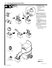
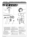
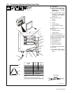
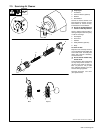
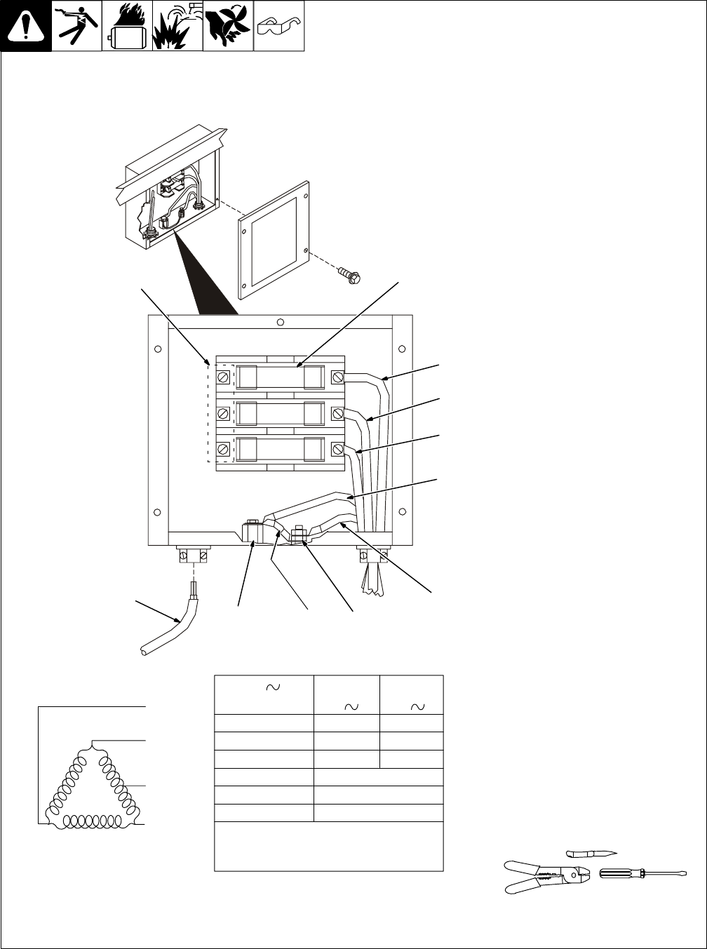
6-3. Connecting Optional Auxiliary Power Plant
Ref. S-188 059-A
Y Stop engine.
Y Power and weld outputs are
live at the same time.
Disconnect or insulate
unused cables.
. Have qualified person install
according to circuit diagram
and Auxiliary Power Guidelines
(Section 10).
Remove junction box cover.
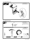
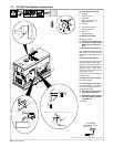
1 Lead 93
2 Lead 92
3 Lead 91
4 Lead 90 (Neutral)
5 Lead 42 (Circuit Grounding
Lead)
Lead 42 connects to front panel
Ground stud.
6 Grounding Terminal
7 Jumper Lead 42
8 Isolated Neutral Terminal
Jumper 42 is connected to lead 90
at factory. Jumper 42 may be dis-
connected from neutral to meet
applicable electrical codes.
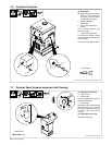
9 User Supplied Leads
10 Load Terminals
Connect leads to terminals.
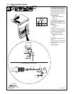
11 Fuses F1, F2, And F3
F1, F2, and F3 protect each load line
from overload.
. Set Engine Control switch to
Run when using auxiliary
power.
92
90
91
93
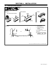
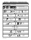
Tools Needed:
F3
F2
F1
3
5
4
678
10
11
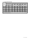
Volts
Amps
KVA/KW
Single
120/240
31
7.5
Three
240
24
10
60 HzFrequency
Engine Speed
Max. Fuse Size 35 Amperes
1850 RPM
AC
Phase
1
Phase
3
Output
Lead 42 connects to GROUND stud on front of
unit.
Jumper 42 is connected to 90 at factory.
1
2
9