


OM-481 Page 18
SECTION 5 – OPERATING THE WELDING GENERATOR
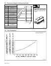
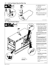
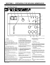
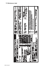
5-1. Front Panel Controls
ST-134 687-B
12 4 5678
9
10
11
12
15 14 13
3
1 Voltmeter
2 Ammeter
3 Ampere Range Switch
Y Do not switch under load.
Use switch to select weld amperage range.
For most welding applications, use lowest
amperage range possible to help prevent arc
outages.
4 Amperage/Voltage Control
Control adjusts amperage within range se-
lected by Ampere Range switch. Example:
weld output would be 90 A DC with Ampere
Range switch in 55 to 125 A DC/CC position
and Amperage/Voltage control set at 50 (50%
of 55 to 125 A).
5 Service Engine Air Cleaner Light
Service engine air cleaner if light goes on (see
Section 7-3).
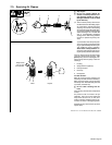
6 Amperage/Voltage Control Switch
Use switch to select front panel or remote am-
perage control (see Section 5-2).
For front panel control, place switch in Panel
position. For remote control, place switch in
Remote position and connect remote control
to Remote 14 receptacle or terminal strip 3T
(see Sections 4-7 and 4-8).
7 CC/CV Selector Switch
Use switch to select type of weld output. Use
CC for Stick (SMAW) welding and Air Carbon
Arc Cutting. Use CV for wire feed processes
(MIG, FCAW, SAW). If using CV, place Am-
pere Range switch in maximum position.
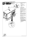
8 Output (Contactor) Switch
Use switch to control remote contactor con-
nected to receptacle RC3 or terminal strip 3T
(see Sections 4-7 and 4-8).
9 Check Cooling System/Alternator Light
Y Stop engine and check engine belt if
light goes on (see Section 7-7).
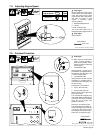
10 Engine Control Switch
Use switch to start engine and stop engine.
In Run position, engine runs at weld/power
speed all the time.
To Start: turn Engine Control switch to Start.
Release switch when engine starts.
. If the engine does not start, let engine
come to a complete stop before attempt-
ing restart.
To Stop: turn Engine Control switch to Off
position. If unit has overspeed shutdown op-
tion, engine stops automatically when speed
exceeds normal rpm.
11 Engine Hour Meter
12 Fuel Gauge
13 Battery Ampere Gauge
Use gauge to check amperage output to the
battery. The gauge reads near 0 (zero) when
the engine is running. If gauge is at a negative
number, the battery is discharging.
Y Stop engine, and do not run until prob-
lem is fixed.
14 Oil Pressure Gauge/Switch
Use gauge/switch to check oil pressure. Nor-
mal operating pressure is about 50 psi (345
kPa). Engine stops if oil pressure is too low.
Y Do not run engine until problem is
fixed.
15 Oil Temperature Gauge/Switch
Use gauge/switch to check oil temperature.
Normal operating temperature is about 225°F
(107° C). Engine stops if oil temperature is too
high.
Y Do not run engine until problem is
fixed.