


OM-481 Page 19
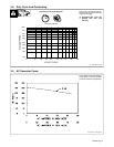
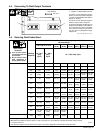
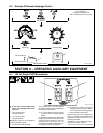
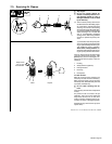
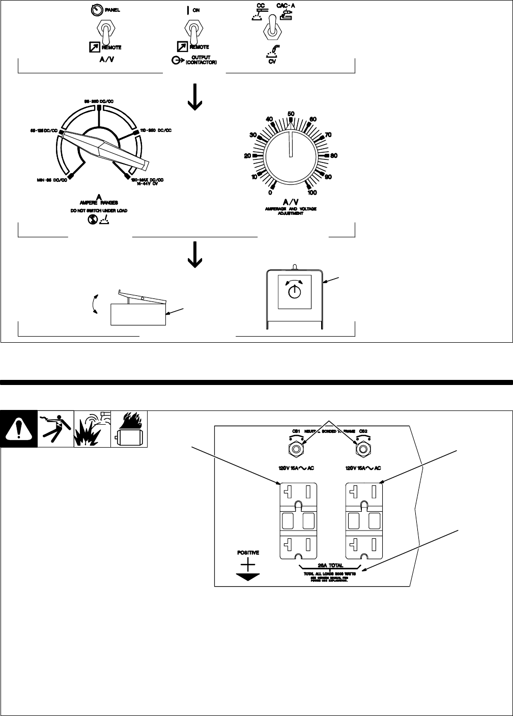
5-2. Example Of Remote Amperage Control
Set Switches
Adjust Remote Control
Set Percentage
Min = 55 A DC/CC
Percentage Of Range = 50%
Max = 90 A DC/CC (50% of 55 to 125)
In Example:
S-0774 / S-0769
Set Range
Min (55 A DC/CC)
Max (90 A DC/CC)
2
3
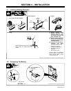
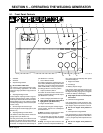
SECTION 6 – OPERATING AUXILIARY EQUIPMENT
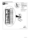
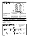
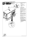
6-1. 120 Volt Duplex GFCI Receptacles
Ref. ST-174 733
Y If unit does not have GFCI recep-
tacles, use GFCI-protected exten-
sion cord.
1 120 V 20 A AC GFCI
Receptacle GFCI1
2 120 V 20 A AC GFCI
Receptacle GFCI2
Receptacles supply 60 Hz single-phase
power at weld/power speed.
3 Circuit Breakers CB1 And CB2
CB1 protects GFCI1 and CB2 protects
GFCI2 from overload. If CB1 or CB2 opens,
the receptacle does not work.
. If a circuit breaker continues to open,
contact a Factory Authorized Service
Agent.
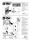
If a ground fault is detected, the GFCI Reset
button pops out and the circuit opens to dis-
connect the faulty equipment. Check for
damaged tools, cords, plugs, etc. con-
nected to the receptacle. Press button to re-
set receptacle and resume operation.
. At least once a month, run engine at
weld/power speed and press Test but-
ton to verify GFCI is working properly.
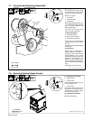
4 Total Generator Power Output
Maximum output from each duplex recep-
tacle is 1.8 kVA/kW, and 3 kVA/kW from all
receptacles. Generator power is not af-
fected by weld output.
EXAMPLE: If 15 A is drawn from GFCI1,
only 10 A is available at GFCI2:
(120 V x 15 A) + (120 V x 10 A) = 3.0 kVA/kW
1
2
3
4