


OM-491 Page 18
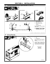
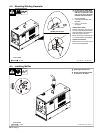
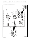
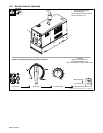
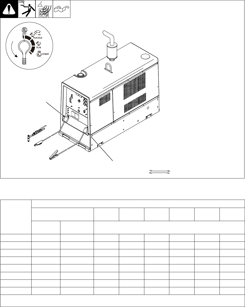
4-8. Connecting To Weld Output Terminals
Ref. 802 169-A
Y Stop engine.
1 Positive (+) Weld Output
Terminal
2 Negative (−) Weld Output Ter-
minal
For Stick and TIG welding Direct
Current Electrode Positive
(DCEP), connect work cable to −
terminal and electrode holder cable
to + terminal.
For Direct Current Electrode Nega-
tive (DCEN), reverse cable
connections.
If equipped with optional polarity
switch, connect electrode holder
cable to Electrode (−) terminal on
left and work cable to Work (+) ter-
minal on right.
Tools Needed:
2
3/4 in
OR
1
4-9. Selecting Weld Cable Sizes
Total Cable (Copper) Length In Weld Circuit Not Exceeding
Welding
Amperes
100 ft (30 m) Or Less
150 ft
(45 m)
200 ft
(60 m)
250 ft
(70 m)
300 ft
(90 m)
350 ft
(105 m)
400 ft
(120 m)
Amperes
10 − 60%
Duty Cycle
60 − 100%
Duty Cycle
10 − 100% Duty Cycle
100 4 4 4 3 2 1 1/0 1/0
150 3 3 2 1 1/0 2/0 3/0 3/0
200 3 2 1 1/0 2/0 3/0 4/0 4/0
250 2 1 1/0 2/0 3/0 4/0 2-2/0 2-2/0
300 1 1/0 2/0 3/0 4/0 2-2/0 2-3/0 2-3/0
350 1/0 2/0 3/0 4/0 2-2/0 2-3/0 2-3/0 2-4/0
400 1/0 2/0 3/0 4/0 2-2/0 2-3/0 2-4/0 2-4/0
500 2/0 3/0 4/0 2-2/0 2-3/0 2-4/0 3-3/0 3-3/0
*Weld cable size (AWG) is based on either a 4 volts or less drop or a current density of at least 300 circular mils per ampere. Contact your
distributor for the mm
2
equivalent weld cable sizes. S-0007-E