


OM-491 Page 32
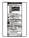
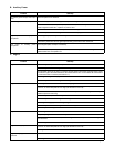
7-9. Troubleshooting
A. Welding
Trouble Remedy
No weld output; auxiliary power output
okay.
Check position of Ampere Range switch.
Check position of optional polarity switch.
Place Amperage Adjust switch in Panel position, or place switch in Remote position and connect remote
control to Remote Amperage Adjust receptacle RC13 (see Sections 4-10 and 5-1).
Check and secure connections to Remote Amperage Adjust receptacle RC13 (see Section 4-10).
Check fuse F2, and replace if open (see Section 7-7). Have Factory Authorized Service Agent check inte-
grated rectifier SR2 and the rotor.
No weld output or auxiliary power output. Disconnect equipment from auxiliary power receptacles during start-up.
Check fuses F1 and F2, and replace if open (see Section 7-7). Have Factory Authorized Service Agent
check integrated rectifier SR1, capacitor C9, integrated rectifier SR2, and the rotor.
Reset circuit breaker CB12. Have Factory Authorized Service Agent check diode D1 (see Section 7-7).
Have Factory Authorized Service Agent check brushes and slip rings, and field excitation circuit.
Erratic weld output. Check and tighten connections inside and outside unit.
Be sure connection to work piece is clean and tight.
Use dry, properly stored electrodes.
Remove excessive coils from weld cables.
Check Ampere Range switch connections and contacts.
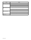
High weld output. Check engine speed, and adjust if necessary.
Have Factory Authorized Service Agent check OCV control circuit.
Low weld output. Check engine speed, and adjust if necessary.
Check fuses F1 and F2, and replace if open (see Section 7-7). Have Factory Authorized Service Agent
check integrated rectifier SR1, capacitor C9, integrated rectifier SR2, and the rotor.
Low open-circuit voltage. Check engine speed, and adjust if necessary.
Maximum weld output only in each
ampere range (with Stick/TIG Selection
switch in Stick position).
Have Factory Authorized Service Agent check control relay CR7.
No remote fine amperage control. Place Amperage Adjust switch in correct position.
Check and secure connections to Remote Amperage Adjust receptacle RC13 (see Section 4-10).
Repair or replace remote control device.
Max OCV circuit does not work (OCV is
adjustable at all times)
Reset circuit breaker CB11 (see Section 7-7). Have Factory Authorized Service Agent check control relay
CR7.
Have Factory Authorized Service Agent check control relay CR7.