


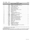
OM-491 Page 53
. Hardware is common and
not available unless listed.
802 278
1
2
3
4
5
6
12
11
10
7
8
9
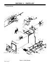
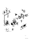
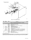
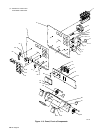
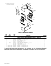
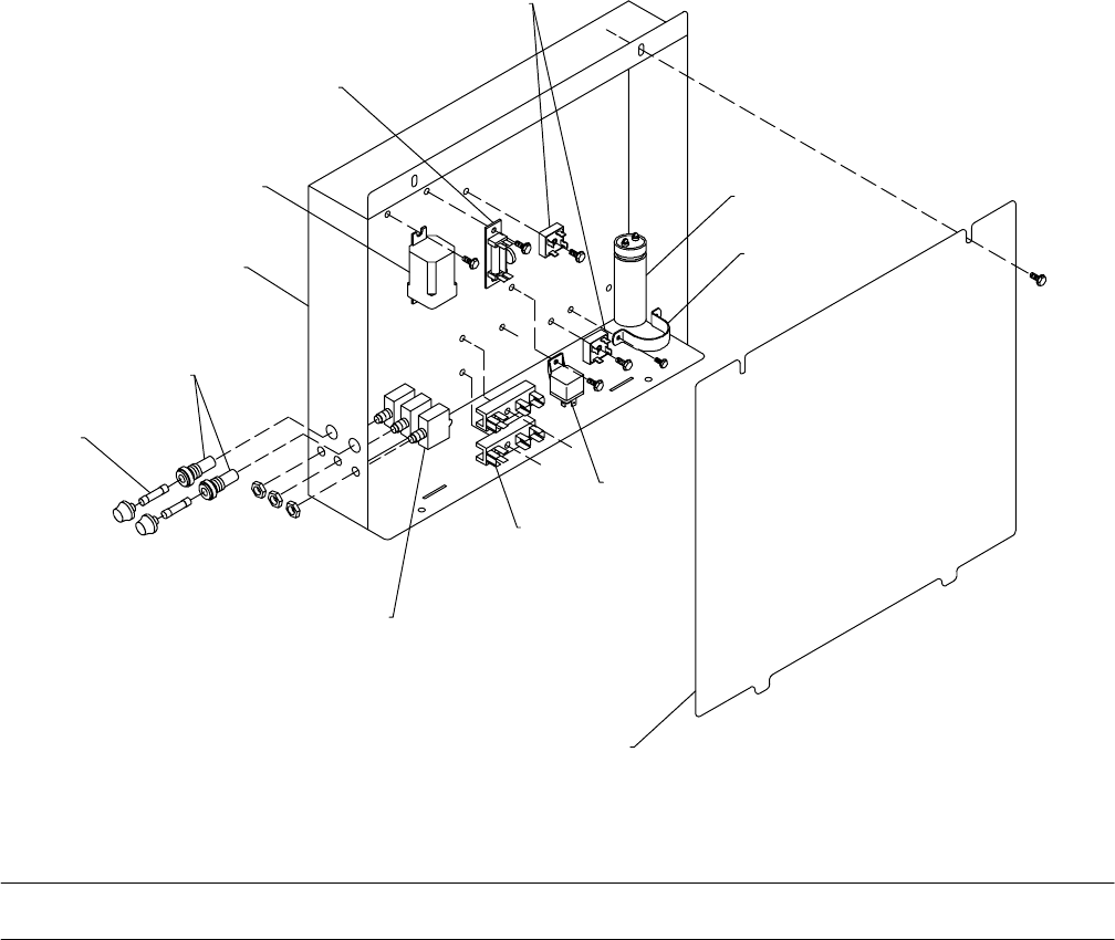
Figure 11-2. Control Box Assembly
Description
Part
No.
Dia.
Mkgs.
Item
No.
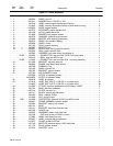
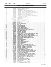
Figure 11-2. Control Box Assembly (Figure 11-1 Item 93)
Quantity
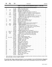
1 F1, F2 *085 874 FUSE, mintr cer slo-blo 10A 250V 2. . . . . . . . . . . . . . . . . . . . . . . . . . . . . . . . . . . . . . . . . . .
2 046 432 HOLDER, fuse mintr .250 x 1.250 2. . . . . . . . . . . . . . . . . . . . . . . . . . . . . . . . . . . . . . . . . . . . . . . . . . .
3 189 385 CONTROL BOX 1. . . . . . . . . . . . . . . . . . . . . . . . . . . . . . . . . . . . . . . . . . . . . . . . . . . . . . . . . . . . . . . . . .
190 253 HARNESS, control box, weld control (consisting of) 1. . . . . . . . . . . . . . . . . . . . . . . . . . . . . . . . . . . . . .
4 CR7 188 636 RELAY, OCV control 1. . . . . . . . . . . . . . . . . . . . . . . . . . . . . . . . . . . . . . . . . . . . . . . . . . . . . . . . .
5 D1/C1 189 701 DIODE/CAPACITOR BOARD 1. . . . . . . . . . . . . . . . . . . . . . . . . . . . . . . . . . . . . . . . . . . . . . .
6 SR1, SR2 035 704 RECTIFIER, integ 40A 800V 2. . . . . . . . . . . . . . . . . . . . . . . . . . . . . . . . . . . . . . . . . . . . . .
7 CR5 090 104 RELAY, encl 12VDC SPST 30A/15VDC 1. . . . . . . . . . . . . . . . . . . . . . . . . . . . . . . . . . . . . . . . .
8 2T, 3T 190 210 BLOCK, term 5-3-3 2. . . . . . . . . . . . . . . . . . . . . . . . . . . . . . . . . . . . . . . . . . . . . . . . . . . . . . . . .
RC5 047 483 CONNECTOR, rect univ 084 15P/S 3 row rcpt cable/panel lkg 1. . . . . . . . . . . . . . . . . . . . . . . .
RC3, RC4 158 466 CONNECTOR, rect univ 084 12P/S 3 row rcpt cable/panel lkg 2. . . . . . . . . . . . . . . . . . . .
RC1, 2, 7 135 133 CONNECTOR, rect univ 084 9P/S 3 row rcpt cable/panel lkg 3. . . . . . . . . . . . . . . . . . . .
9 CB11, 12, 13 139 266 CIRCUIT BREAKER, man reset 1P 15A 250VAC frict 3. . . . . . . . . . . . . . . . . . . . . .
10 189 386 COVER, control box 1. . . . . . . . . . . . . . . . . . . . . . . . . . . . . . . . . . . . . . . . . . . . . . . . . . . . . . . . . . . . . . .
11 177 136 CLAMP, capacitor 1.375dia 1. . . . . . . . . . . . . . . . . . . . . . . . . . . . . . . . . . . . . . . . . . . . . . . . . . . . . . . . .
12 C9 087 110 CAPACITOR, elctlt 240uf 200VDC 1. . . . . . . . . . . . . . . . . . . . . . . . . . . . . . . . . . . . . . . . . . . . . . . .
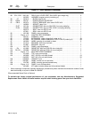
*Recommended Spare Parts.
To maintain the factory original performance of your equipment, use only Manufacturer’s Suggested
Replacement Parts. Model and serial number required when ordering parts from your local distributor.