


OM-175 104 Page 8
SECTION 4 – OPERATING WELDING GENERATOR
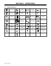
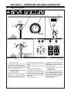
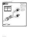
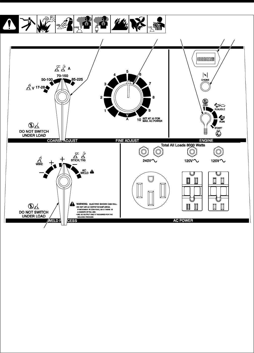
4-1. Front Panel Controls
Ref. ST-178 079-A
1 Engine
Control Switch
Use switch to start engine, select speed,
and stop engine. In Run/Idle position, en-
gine
runs at idle speed at no
load, and weld/
power speed under load. In Run position,
engine
runs at weld/power speed.
.
Place
switch in Run position to operate
most GMA
W equipment.
2
Engine Choke Control
Use control to change engine air-fuel mix.
To Start: pull out choke and turn Engine
Control switch to Start position. Release
switch and slowly push choke in when en-
gine
starts. Do not crank engine if engine
is
still
turning. Set anti-icing control (see Sec
-
tion
3-4).
To Stop: turn Engine Control switch to Off
position.
3 Weld Process Selector Switch
Use switch to select type of weld output.
Use
a positive
(+) position for Direct Current
Electrode Positive (DCEP) and a negative
(–) position for Direct Current Electrode
Negative
(DCEN). Use AC position for
alter
-
nating
current.
4 Coarse Adjust Switch
Use switch to select weld amperage range
when Weld Process Selector switch is in
Stick/Tig position, or voltage range when
switch
is in Wire position.
.
For best arc starts, use lowest amper-
age
range possible.
5
Fine Adjust Control
Use
control to select weld amperage (Stick/
Tig) or voltage (Wire) within the range se-
lected
by the Coarse Adjust switch. Control
may
be adjusted while welding. W
eld output
would be 110 A DC based on control set-
tings
shown (50% of 70 to 150 A).
6
Engine Hour Meter
5 2
3
1 64