


OM-175 104 Page 5
SECTION 3 – INSTALLATION
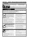
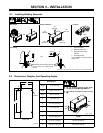
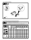
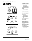
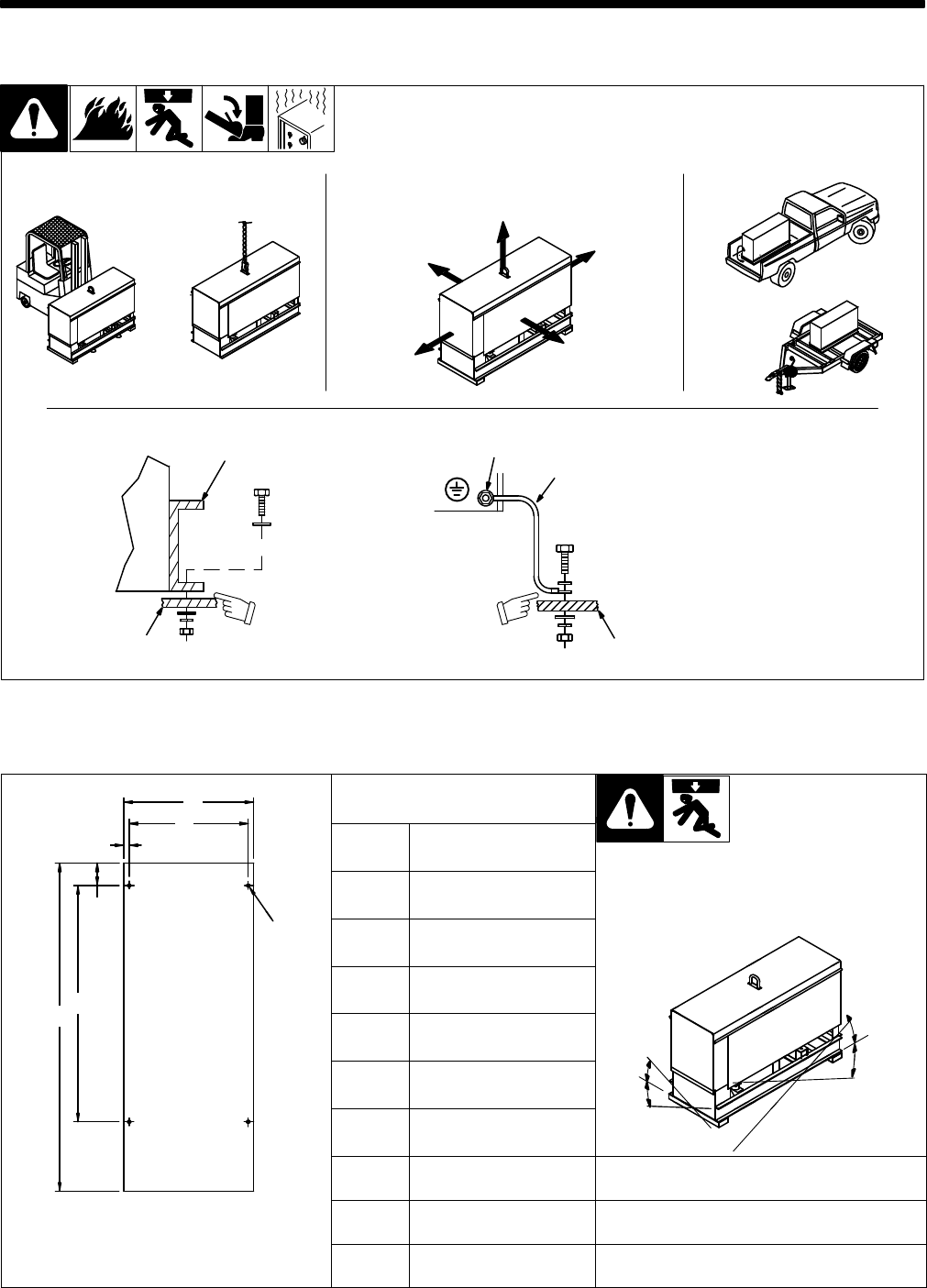
3-1. Installing Welding Generator
install1* 3/96 – Ref. ST-800 652 / Ref. ST-800 477-A / ST-158 936-A / S-0854
1
2
Electrically
bond
generator frame to
vehicle frame by metal-to-metal
contact.
GND/PE
3
4
1 Generator Base
2
Metal V
ehicle Frame
3
Equipment Grounding
Terminal
4
Grounding Cable
Use #10 AWG or larger insulated
copper
wire.
2
OR
18 in
(460 mm)
18 in
(460 mm)
18 in
(460 mm)
18 in
(460 mm)
18 in
(460 mm)
OR
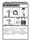
Movement Airflow Clearance Location
Grounding
OR
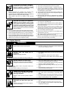
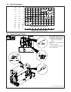
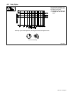
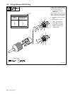
3-2. Dimensions, Weights, And Operating Angles
A
B
Dimensions
B
C
Height
31 in (787 mm)
Y Do not exceed operating angles while
i
i d ill
D
Width
18-3/4 in (476 mm)
Y Do
not
exceed
operating
angles
while
running
or engine damage will occur
.
Y Do
not move or operate unit where it could
tip
4 Holes
G
Depth
46 in (1
164 mm)
tip.
E
F
A
18 in (457 mm)
25°
E
F
B
16-1/2 in (419 mm)
25°
25
°
°
C
3/4 in (19 mm)
25°
25°
25°
D
3-1/8 in (79 mm)
angles_1 3/96
E
32-3/4 in (832 mm)
Weight
Engine End
F
45-1/2 in (1
156 mm)
Net: 567 lb (258 kg)
ST-800 426
G
13/32 in (10 mm) Dia.
Ship: 608 lb (276 kg)