


OM-220 812 Page 9
SECTION 3 − INSTALLATION
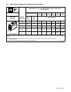
3-1. Specifications
Welding
Mode
Input
Power
Rated
Output
Welding
Amperage
Range
Maximum
Open-Circuit
Voltage
Amperes Input At Rated Load
Output, 50/60 Hz
KVA KW Dimensions
Net
Weight
Range Voltage
220 400 440
KVA
KW
Dimensions
W
e
i
g
ht
3-Phase
250 A @
30 VDC,
50 % Duty
Cycle
5-250 A
30 VDC
32.1 18.2 16.4 12.3 8.7
Stick
3
-
Ph
ase
200 A @
28 VDC,
100 %
Duty Cycle
5-
2
5
0 A
30 VDC
24.2 14.4 12.6 9.9 6.5
H: 13-1/2 in
(343 mm)
W: 7-1/2 in
40 lb
Stick
(SMAW)
1-Phase
200 A @
28 VDC,
50 % Duty
Cycle
5-200 A
30 VDC
42.6 n/a n/a 10.0 6.6
W: 7 1/2 in
(191 mm)
D: 18 in (457
mm)
40 lb
(18.2 kg)
1
-
Ph
ase
150 A @
26 VDC,
100 %
Duty Cycle
5-
200 A
30 VDC
33.6 n/a n/a 7.4 5.7
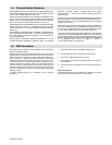
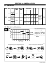
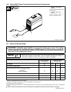
3-2. Duty Cycle And Overheating
Duty Cycle is percentage of 10
minutes that unit can weld at rated
load without overheating.
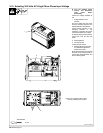
If unit overheats, output stops, and
cooling fan runs. Wait fifteen
minutes for unit to cool. Reduce
amperage or duty cycle before
welding.
Y Exceeding duty cycle can
damage unit and void
warranty.
200 A @ 50% Duty Cycle For Single Phase Operation
Overheating
0
15
A or V
OR
Reduce Duty Cycle
Minutes
250 A @ 50% Duty Cycle For 3 Phase Operation
5 Minutes Welding 5 Minutes Resting5 Minutes Welding 5 Minutes Resting
206 173