


OM-220 812 Page 37
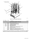
. Hardware is common and
not available unless listed.
Ref. 803 162
1
2
3
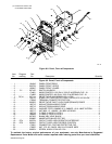
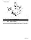
Figure 8-7. Heat Sink Assembly, Input
Description
Part
No.
Dia.
Mkgs.
Item
No.
Figure 8-7. Heat Sink Assembly, Input
Quantity
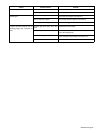
1 205915 HEAT SINK,IGBT/INPUT RECTIFIER MODULE 1. . . . . . . . . . . . . . . . . . . . . . . . . . . . . . . . . . . . . . .
2 206091 BRACKET,HEATSINK REAR 1. . . . . . . . . . . . . . . . . . . . . . . . . . . . . . . . . . . . . . . . . . . . . . . . . . . . . . . .
3 TE1 206328 BLOCK,TERM 70 AMP 3 POLE SCREW TERM 4−14 WIRE 1. . . . . . . . . . . . . . . . . . . . . . .
To maintain the factory original performance of your equipment, use only Manufacturer’s Suggested
Replacement Parts. Model and serial number required when ordering parts from your local distributor.