


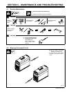

OM-220 812 Page 18
Y Disconnect and lockout/tag-
out input power before
connecting input conduc-
tors from unit.
Y Have only qualified persons
make this installation.
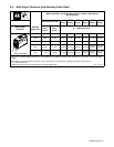
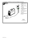
See rating label on unit and check
input voltage available at site.
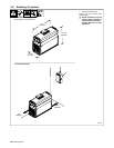
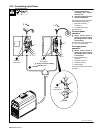
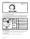
1 Input And Grounding
Conductors
2 Line Disconnect Device
See Section 3-9.
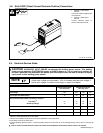
For three-phase
operation:
Y Always connect green or
green/yellow wire to supply
grounding terminal, never to
a line terminal.
Connect black, white, and red wires
(L1, L2, L3) to line terminals.
For single-phase
operation:
Y Always connect green or
green/yellow wire to supply
grounding terminal, never to
a line terminal.
3 Black And White Input
Conductor
4 Red Input Conductor
5 Insulation Sleeving
6 Electrical Tape
Insulate and isolate red conductor
as shown.
L1
2
2
1
1
3
1
6
5
4
L2
L3
L1
L2
Y Always connect grounding
conductor first
1
3
= GND/PE
Green Or
Green/Yellow
Green Or
Green or
Green/Yellow
input_2 3/96 - 803 080
3-12. Connecting Input Power
Green/Yellow