


OM-220 812 Page 15
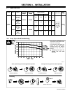
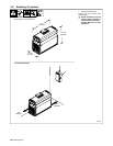
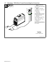
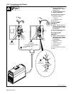
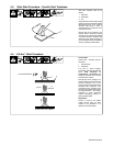
3-8. Stick DCEP (Direct Current Electrode Positive) Connections
Ref. 802 888 / Ref. 803 080
1 Negative (−) Weld Output
Terminal
Connect work lead to negative weld
output terminal.
2 Positive (+) Weld Output
Terminal
Connect electrode holder to
positive weld output terminal.
1
2
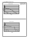
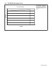
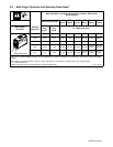
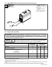
3-9. Electrical Service Guide
Y CAUTION: INCORRECT INPUT POWER can damage this welding power source. This welding
power source requires a CONTINUOUS supply of 50/60 Hz power at +10% of rated input voltage. Do
not use a generator with automatic idle device (that idles engine when no load is sensed) to supply
input power to this welding power source.
Actual input voltage cannot exceed ± 10% of indicated required input voltage. If
actual input voltage is outside of this range, no output is available.
NOTE
50/60 Hz Single-Phase,
50% Duty Cycle
50/60 Hz Three-Phase,
50% Duty Cycle
Input Voltage 220 220 400 440
Input Amperes At Rated Output 45 32 18 16
Max Recommended Standard Fuse Rating In Amperes
1
Time-Delay
2
50 40 20 20
Normal Operating 3 70 50 25 25
Min Input Conductor Size In AWG/Kcmil 8 10 14 14
Max Recommended Input Conductor Length In Feet (Meters) 129 (39) 132 (40) 174 (53) 210 (64)
Min Grounding Conductor Size In AWG/Kcmil 8 10 14 14
Reference: 2002 National Electrical Code (NEC)
1 Choose a circuit breaker with time-current curves comparable to a Time Delay Fuse.
2 “Time-Delay” fuses are UL class “RK5” .
3 “Normal Operating” (general purpose − no intentional delay) fuses are UL class “K5” (up to and including 60 amp), and UL class “H” ( 65 amp and
above).
Y Caution: Failure to follow these fuse and circuit breaker recommendations could create an electric shock or fire hazard.