


OM-2252 Page 19
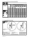
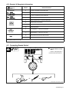
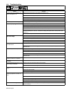
4-10. Remote 14 Receptacle Information
Socket* Socket Information
24 VOLTS AC
A 24 volts ac. Protected by circuit breaker CB2.
B Contact closure to A completes 24 volts ac contactor control circuit.
115 VOLTS AC
I 115 volts ac. Protected by circuit breaker CB1.
J Contact closure to I completes 115 volts ac contactor control circuit.
C Output to remote control; +10 volts dc in MIG mode.
REMOTE
OUTPUT
D Remote control circuit common.
OUTPUT
CONTROL
E 0 to +10 volts dc input command signal from remote control.
M Remote mode select.
A/V
AMPERAGE
F Current feedback; +1 volt dc per 100 amperes.
AMPERAGE
VOLTAGE
H Voltage feedback; +1 volt dc per 10 arc volts.
GND
G Circuit common for 24 and 115 volts ac circuits.
GND
K Chassis common.
*The remaining sockets are not used.
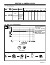
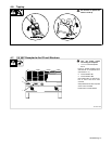
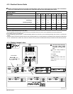
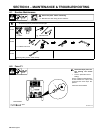
4-11. Connecting Remote Control
Ref. 800 166-D / Ref. S-0004-A / S-0750
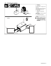
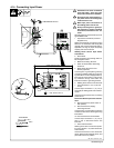
! Turn off power before con-
necting to Remote 14 recep-
tacle.
1 Remote 14 Receptacle RC14
Connect remote control to RC14.
AJ
B
K
I
C
L
NH
D
M
G
E
F
1
OR
OR