


OM-2252 Page 20
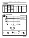
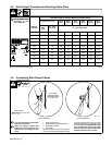
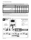
4-12. Electrical Service Guide
Failure to follow these electrical service guide recommendations could create an electric shock or fire hazard. These recommenda-
tions are for a dedicated branch circuit sized for the rated output and duty cycle of the welding power source.
50/60 Hertz Models
Input Voltage 230 380 400 440 460 575
Input Amperes At Rated Output 57 34 33 30 29 23
Max Recommended Standard Fuse Rating In Amperes
1
Time-Delay
2
70 40 40 35 35 25
Normal Operating 3 90 50 50 45 40 35
Min Input Conductor Size In AWG
4
6 8 8 10 10 10
Max Recommended Input Conductor Length In Feet (Meters) 145 (44) 256 (78) 284 (86) 226 (69) 243 (74) 380 (116)
Min Grounding Conductor Size In AWG
4
8 10 10 10 10 10
Reference: 2005 National Electrical Code (NEC)
1 If a circuit breaker is used in place of a fuse, choose a circuit breaker with time-current curves comparable to the recommended fuse.
2 “Time-Delay” fuses are UL class “RK5” .
3 “Normal Operating” (general purpose − no intentional delay) fuses are UL class “K5” (up to and including 60 amp), and UL class “H” ( 65 amp and
above).
4 Conductor data in this section specifies conductor size (excluding flexible cord or cable) between the panelboard and the equipment per NEC Table
310.16. If a flexible cord or cable is used, minimum conductor size may increase. See NEC Table 400.5(A) for flexible cord and cable requirements.
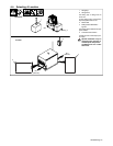
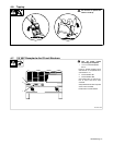
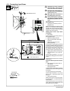
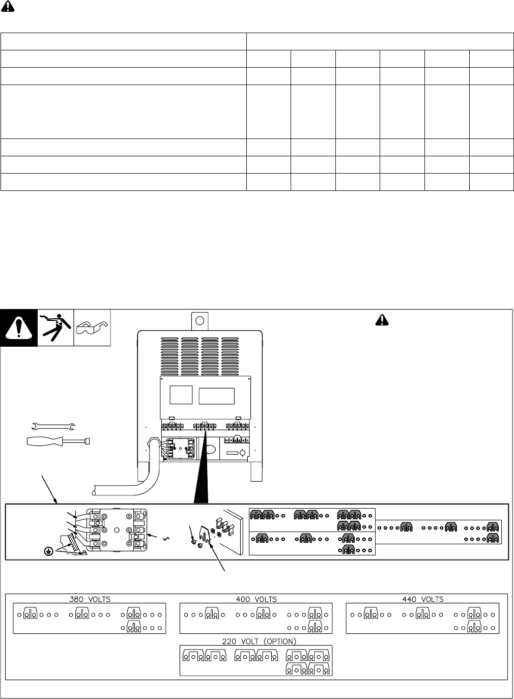
4-13. Placing Jumper Links
Ref. 800 103-A
! Disconnect and lockout/tag-
out input power before
installing or moving jumper
links.
Check input voltage available at
site.
1 Jumper Link Label
Check label.
2 Jumper Links
Move jumper links to match input
voltage.
Close access door, or go on to
Section 4-14.
Tools Needed:
1
3/8 in
3/8 in
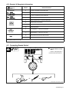
L1 (U)
S−174 973−B
GND/ PE
3
Connect
GND/PE
Conductor
First.
I nput
Con t actor
L2 (V)
L3 (W)
230 VOLTS
460 VOLTS
575 VOLTS
Do not
overtighten
jumperlinknuts.
2