


OM-2252 Page 26
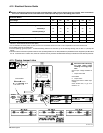
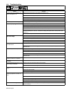
6-4. Troubleshooting
Trouble Remedy
No weld output; unit completely inop-
erative; pilot light PL1 off.
Place line disconnect device in On position (see Section 4-14).
Check for open line fuse(s), and replace if open (see Section 4-14).
Check for proper input power connections (see Section 4-14).
Check for proper jumper link position (see Section 4-13).
Check fuse F1, and replace if necessary (see Section 6-2).
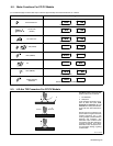
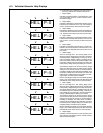
Meter displays a HELP message. If meters display a HELP message, see Section 6-3.
No weld output; pilot light PL1 on.
Check for open line fuse(s), and replace if open (see Section 4-14).
pp g
Check for proper input power connections (see Section 4-14).
Check for proper jumper link position (see Section 4-13).
Unit overheated. Allow unit to cool with fan On (see Section 4-2).
If using remote control, place Panel/Remote control switch in Remote position, and connect remote
control (see Sections 4-11 and 5-1). If remote is not being used, place switch in Panel position (see
Section 5-1).
Check, repair, or replace remote control.
Limited weld output and low
open-circuit voltage
Check position of Panel/Remote control switch (see Section 5-1).
open-circuit voltage.
Check for open line fuse(s), and replace if open (see Section 4-14).
Check for proper input power connections (see Section 4-14).
Check for proper jumper link position (see Section 4-13).
Clean and tighten all weld output connections.
Unit provides only maximum or mini-
mum weld output.
Check position of Panel/Remote control switch (see Section 5-1).
Have Factory Authorized Service Agent check control board PC1, front panel display board PC2, and
hall device HD1.
Erratic or improper weld output. Use proper size and type of weld cable (see Section 4-8).
Clean and tighten all weld connections.
Check wire feeder installation according to Owner’s Manual.
Check position of Mode switch (see Section 5-1).
Have Factory Authorized Service Agent check control board PC1, front panel display board PC2, and
hall device HD1.
No 115 volts AC output at duplex re-
ceptacle or Remote 14 receptacle.
Reset circuit breaker CB1 (see Section 4-7).
No 24 volts AC output at Remote 14
receptacle.
Reset circuit breaker CB2 (see Section 4-7).
Fan not operating. Note: fan only runs
when cooling is necessary.
Check for and remove anything blocking fan movement.
Have Factory Authorized Service Agent check fan motor.
Wandering arc; poor control of arc di-
rection.
Reduce gas flow rate.
Select proper size tungsten.
Properly prepare tungsten.
Tungsten electrode oxidizing and not
remaining bright after conclusion of
weld.
Shield weld zone from drafts.
Increase postflow time.
Check and tighten all gas fittings.
Properly prepare tungsten.
Check for water in torch, and repair torch if necessary. See torch Owner’s Manual.
Digital meter not working properly. Have Factory Authorized Service Agent check front panel display board PC2 and connections, and re-
place if necessary.