


SECTION 4 MAINTENANCE AND REPAIR
OM-179 078 4-1
4.1 MAINTENANCE REQUIREMENTS
The DWF–3 wire feed system has no special scheduled maintenance requirements. However, periodic
inspection of control and wire drive are helpful in preventing equipment failures. Replace any worn or broken
parts found. Periodic dust and oil removal from both the control and drive is recommended.
4.2 GENERAL PRECAUTIONS
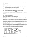
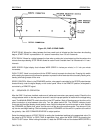
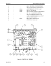
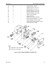
Figure 4.1 shows a control unit for the DWF–3 system. Assemblies and parts which are authorized for user
replacement are listed in Table 4.1. Should the user experience a problem and determine the defective part
(see TROUBLESHOOTING, Section 4.5), the suggested repair procedure is to remove and replace the
defective part.
CAUTION
WHEN INSPECTING OR REPAIRING THE CONTROL UNIT ASSEMBLY, DISCONNECT AC POWER
FROM THE UNIT BEFORE REMOVING THE COVER TO PREVENT ELECTRICAL SHOCK.
4.3 CONTROL UNIT CALIBRATION
The control unit has been calibrated and fully tested before leaving the factory. It is unlikely that it would
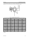
require adjustment; however, if the need for recalibration arises, there are three adjustments that can be
made that affect wire speed and delay time accuracy. The only test equipment required is a good quality
frequency counter of known accuracy. Two adjustments, R2 and R7 on Controller/Driver circuit board affect
wire speed accuracy. Perform the following steps to calibrate the control unit.
A) Connect the frequency counter to TP14.
B) Rotate the speed control knob on the front panel to its minimum speed setting, i.e., fully
counterclockwise.
C) Adjust R7 until the frequency counter indicates zero.
D) Repeat Steps B and C. There is only one adjustment to be made on the time base osc. – R10; it sets the
start and stop delay accuracy and the wire speed readout accuracy.
E) Connect the frequency counter to TP2, and adjust R10 for a reading of 2560 Hz ± 1 Hz.
NOTE: REPEAT STEPS B THROUGH E IF THE ADJUSTMENT ON R10 IS CHANGED.
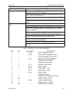
TABLE 4.1 PARTS LIST FOR CONTROL UNIT
ITEM QTY PART NMBR DESCRIPTION
1 1 179 186 CHASSIS ASSEMBLY
2 1 179 188 PWB DWF–3 CONTROLLER/DRIVER
3 1 179 189 PWB DWF–3 DISPLAY AND DRIVER
41 – TRANSFORMER ASSY, DWF–3
51 – ASSY, THUMBWHEEL SWITCH
61 – ASSY, THUMBWHEEL SWITCH
71 – CABLE ASSY, DWF–3 INTERNAL INTERFACE