


SECTION 4 MAINTENANCE AND REPAIR
OM-179 078 4-4
TROUBLE INDICATION
REPAIR STEPS
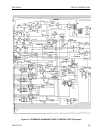
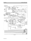
Incorrect wire feed speed. Check input signal (TP15 on Controller/Driver circuit board). Replace
speed pot or circuit board if necessary.
Verify that thumbscrew is fully seated. Exception: Back off one full turn
when using .020 in diameter wire.
Verify that correct drive rolls for wire diameter are installed (see Table
1.1).
Check roller surface; if excessively worn, slip of urethane wheels and
replace.
Motor turns but wire does not Verify that drive unit is connected to control.
feed.
Verify that all plugs are installed in the circuit board.
Check motor and cable continuity. It should be about 1.5 ohms from
pin A, D, E, and C referenced to pin B on motor connector. Repair or
replace if necessary.
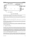
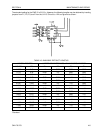
Check motor current (speed less than 10 ipm = 80 to 110 mV between
TP7 and TP8. See Figure 4.2) Replace circuit board if necessary.
Loosen feed tension adjustment knob completely. Verify wire runs
smoothly off wire reel and through guides and conduit.
Verify thumbscrew is properly adjusted. Exception: Back off one full
turn when using .020 in diameter wire.
Verify correct drive rolls for wire diameter (see Table 1.1).
Check roller surface; if excessively worn, slip off urethane wheels and
replace.
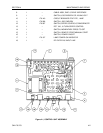
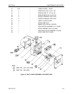
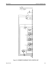
TABLE 4.2 PARTS LIST FOR DRIVE ASSEMBLY
ITEM QTY PART NMBR DESCRIPTION
1 1 179 168 BOGIE ASSEMBLY, DWF–3
2 1 179 169 DRIVE MOTOR ASSEMBLY, DWF–3
31 – COVER ASSEMBLY, DRIVE DWF–3
4 2 179 170 URETHANE ROLLER ASSEMBLY
51 – HOUSING, WIRE FEEDER
61 – RETAINER, DRIVE GEAR
7 2 179 171 BUSHING, GEAR SHAFT
8 2 179 172 SHAFT, BOGIE
9 1 179 173 GUIDE, WIRE – EXIT
10 1 179 174 GUIDE, WIRE – INLET
11 1 179 175 KNOB, SCREW
12 1 – CLAMP, BACKSHELL
13 1 – CONNECTOR, CIRCULAR STR PLUG
14 A/R – TUBING SHRINK, BLACK
15 1 179 176 SPRING COMPRESSION
16 2 – STRAIN RELIEF – PLASTIC
17 A/R – TUBING SHRINK – BLACK