


SECTION 4 MAINTENANCE AND REPAIR
OM-179 078 4-3
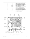
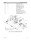
4.4 DRIVE UNIT ASSEMBLY
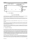
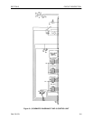
Figure 4.2 shows an exploded view of the drive unit; user replaceable parts are listed in Table 4.2.
4.5 TROUBLESHOOTING
WARNING
LINE VOLTAGE IS EXPOSED INSIDE THE CONTROL UNIT. TAKE PRECAUTION TO AVOID ELECTRIC
SHOCK WHEN COVER IS REMOVED.
The TROUBLESHOOTING section of this manual is not intended to be a step–by–step guide to problem
solving of all possible failure modes. It is intended to point the way to areas which are most likely to cause
difficulties. All repairs should be referred to a qualified technician.
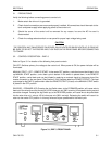
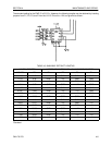
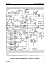
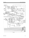
Refer to Figure 5.1 (DWF–3 schematic) and also Figure 4.1 to aid in locating components and test points.
The CIRCUIT DESCRIPTION section (5.1 – 5.4) of this manual should prove helpful in isolating problems.
Some possible trouble areas may be verified by following the repair steps indicated below and on the following
pages.
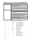
TROUBLE INDICATION REPAIR STEPS
Power ON lamp does not light. Verify that power cord is plugged in and circuit breaker is reset.
Verify that all plugs are installed in the circuit board.
Check +20 V (TP 9 on Controller/Driver circuit board). Replace board if
necessary.
Check lamp; replace if necessary.
Digital display does not light. Verify that power cord is plugged in and circuit breaker is reset.
Verify that all plugs are installed in the circuit board.
Check +20 V (TP 9 on Controller/Driver circuit board). Replace board if
necessary.
Check +5 V (TP 12 on Controller/Driver circuit board). Replace board if
necessary.
Replace digital display board.
Incorrect START/STOP de- Verify that all plugs are installed in the circuit board.
lays.
Recalibrate (see Section 4.3).
Replace thumbwheel assembly or circuit board.
Feed cycle does not start. Verify that MANUAL START/OFF/REMOTE switch is in correct posi-
tion.
Verify that all plugs are installed in the circuit board.
Replace circuit board.
Incorrect wire feed speed. Verify that SPEED CONTROL switch is in correct position.
Verify that all plugs are installed in the circuit board.
Recalibrate (see Section 4.3).