


OM-530 Page 11
AJ
B
K
I
C
L
NH
D
M
G
E
F
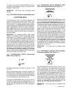
Ref. S-0004-A
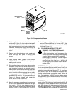
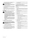
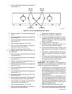
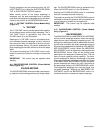
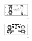
Figure 3-4. Front View Of REMOTE 14 Receptacle
With Socket Locations
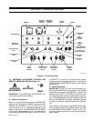
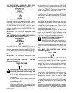
3-11. GAS CONNECTIONS (Figure 4-1)
GAS IN GAS OUT
The GAS IN and GAS OUT fittings have 5/8-18 right-
hand threads. Obtain proper size, type, and length
hose, and make connections as follows:
1. Connect hose from shielding gas supply regulator/
flowmeter to GAS IN fitting.
2. Connect shielding gas hose from torch to GAS OUT
fitting.
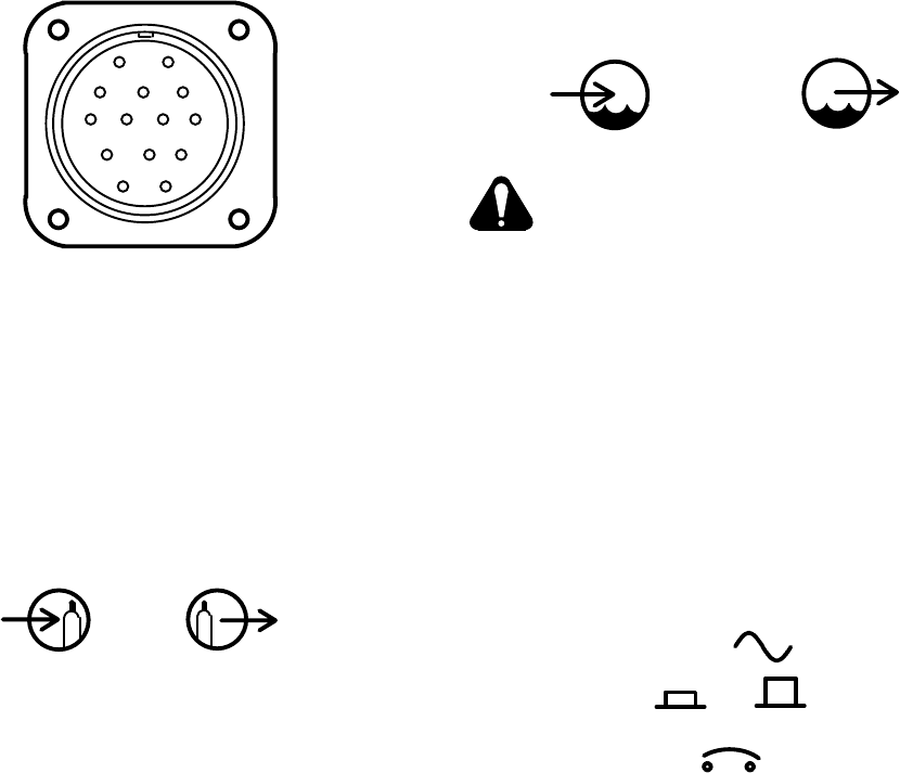
3-12. COOLANT CONNECTIONS (Optional)
(Figure 4-1)
COOLANT IN COOLANT OUT
CAUTION: OVERHEATING Gas Tungsten
Arc Welding (GTAW) torch can damage
torch.
• If using a water-cooled torch and recirculating
coolant system, make connections from the
coolant system directly to the torch hoses. Do
not use water connections on the TIG-Unit.
The COOLANT IN and COOLANT OUT fittings have
5/8-18 left-hand threads. Obtain proper size, type, and
length hose, and make connections as follows:
1. Connect hose from coolant supply to COOLANT IN
fitting.
2. Connect coolant hose from torch to COOLANT
OUT fitting.
3-13. 115 VOLTS AC DUPLEX RECEPTACLE AND
CIRCUIT BREAKER (Figure 4-1)
ON OFF
115V 15A AC
OVERLOAD
PRESS TO START
A grounded duplex receptacle, located behind the front
access door of the TIG-Unit, is provided to furnish up to
2 kva of 115 volts ac to operate external accessories. A
15 ampere circuit breaker, located next to the recep-
tacle, protects this circuit in case overloading of the du-
plex receptacle occurs.