


OM-530 Page 12
SECTION 4 – OPERATOR CONTROLS
TB-059 588-A
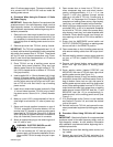
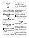
Amperage
Adjustment
Control
Remote
Amperage
Switch
Polarity
Switch
♦Meters ♦Pulser
Postflow
Control
Gas/Coolant
Switch
High
Frequency
Control
High
Frequency
Switch
Circuit Breaker
(See Section 6-4)
115 Volts AC
Duplex Receptacle
Gas Valve
Outlet
Gas Valve
Inlet
Electrode
Output
Terminal
♦Spot Time
Control And
Switch
♦Preflow Time
Control And
Switch
Work
Output
Terminal
♦Electroslope
Remote 14
Receptacle
Interconnecting
Cord
Coolant Valve
Inlet
Coolant Valve
Outlet
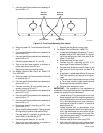
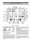
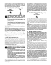
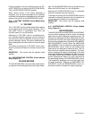
Figure 4-1. Front Panel View
4-1. AMPERAGE ADJUSTMENT CONTROL AND
REMOTE AMPERAGE SWITCH (Figure 4-1)
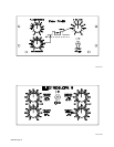
A
AMPERAGE
A
ADJUSTMENT
AMPERAGE
PANEL
14
IMPORTANT: The AMPERAGE ADJUSTMENT con-
trol may be adjusted while welding.
A. Without Electroslope
When not using an Electroslope and the AMPERAGE
switch on the TIG-Unit is in the PANEL position, the AM-
PERAGE ADJUSTMENT control on the TIG-Unit al-
ways functions as a fine amperage adjustment (cali-
brated in percent) of the AMPERAGE ADJUSTMENT
control on the welding power source. If a remote control
is used and the AMPERAGE switch on the TIG-Unit is in
the REMOTE 14 position, the remote control always
functions as a fine amperage adjustment (in percent) of
the AMPERAGE ADJUSTMENT control on the welding
power source.
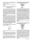
B. With Electroslope
IMPORTANT: For the TIG-Unit to function properly, en-
sure the the AMPERAGE control switch on the welding
power source is always in the REMOTE 14 position. The
position of the OUTPUT (CONTACTOR) control switch
on the welding power source is determined by the situa-
tion. If Remote Contactor Control is desired, place the
switch in the REMOTE 14 position. If Remote Contactor
Control is not desired, place the switch in the ON posi-
tion.
When using an Electroslope, the AMPERAGE switch
on the TIG-Unit must be in the PANEL position and then
the AMPERAGE ADJUSTMENT control on the TIG-
Unit has complete control of the current of the welding
power source.