


OM-530 Page 2
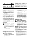
Table 2-1. Specifications
Model
Rated
Amperes
Rated
Duty Cycle
Weight
TIG-Unit
TIG-Unit 56
400
600
60%
60%
175 lbs.
(79.4 kg)
183 lbs.
(83.9 kg)
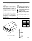
2-1. DESCRIPTION
The TIG-Unit is an accessory package which enables
the solid-state welding power source to provide Gas
Tungsten Arc (GTAW) as well as Shielded Metal Arc
Welding (SMAW) capability. This unit has high frequen-
cy, polarity switch, gas and water valves, postflow timer,
and 115 volts ac auxiliary power as standard, with me-
ters, electroslope, pulser, preflow timer, and spot timer
as options.
SECTION 3 – INSTALLATION OR RELOCATION
IMPORTANT: Read entire Section 8 on equipment that
produces output in the radio frequency range, such as
high-frequency starters, for site selection information
and installation requirements before beginning the in-
stallation procedures.
3-1. SITE SELECTION
Even though the TIG-Unit is an accessory package pro-
viding Gas Tungsten Arc Welding (GTAW) capability for
the solid-state welding power source, it is recom-
mended that certain practices and procedures be fol-
lowed to aid long life and efficient operation.
The TIG-Unit for 300 and 400 ampere welding power
sources is convection-cooled. It does not have or need a
fan to aide the cooling process. The TIG-Unit for 500
and 600 ampere welding power sources is fan-cooled.
However, it is recommended that a suitable location be
chosen to provide adequate airflow, not only for the
welding power source, but for the TIG-Unit as well. See
welding power source Owner’s Manual for proper instal-
lation site information.
WARNING: RESTRICTED AIRFLOW can
cause overheating and possible damage to
internal parts.
• Maintain at least 18 inches (457 mm) of
unrestricted space on all sides of unit, and keep
underside free of obstructions.
• Do not place any filtering device over the in-
take air passages that provide airflow for cooling
this unit.
Warranty is void if any type of filtering device is
used at intake air passages.
3-2. TRANSPORTING METHODS
This unit is equipped with a lifting eye for moving during
installation. Weight capacity of the lifting eye only allows
for supporting the unit and welding power source.
WARNING: ELECTRIC SHOCK can kill.
• Do not touch live electrical parts.
• Disconnect input power conductors from
deenergized supply line BEFORE moving unit
and welding power source.
FALLING EQUIPMENT can cause serious
personal injury and equipment damage.
• Use lifting eye to lift unit only, NOT running
gear, gas cylinders, or any other heavy
accessories or devices.
• Use equipment of adequate capacity to lift
the unit.
• If lifting or moving this unit with lift forks under
the base, be sure that lift forks are long enough
to extend beyond opposite side of the base.
Using lift forks too short can damage internal
parts if tips of the lift forks penetrate the unit
base, or may cause personal injury and/or
equipment damage if unit falls off the lift forks.
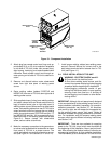
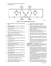
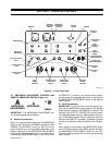
3-3. COMPONENT INSTALLATION ON FACTORY
INSTALLED UNITS (Figure 3-1)
WARNING: ELECTRIC SHOCK can kill.
• Do not touch live electrical parts.
• Shut down welding power source, and dis-
connect input power employing lockout/tagging
procedures before inspecting or installing.
Lockout/tagging procedures consist of pad-
locking line disconnect switch in open position,
removing fuses from fuse box, or shutting off
and red-tagging circuit breaker or other discon-
necting device.
IMPORTANT: Read entire Section 8 on equipment that
produces output in the radio frequency range, such as
high-frequency starters, for site selection information
and installation requirements before beginning the in-
stallation procedures.
The TIG-Unit was shipped installed on and wired into
the welding power source. To prepare the TIG-Unit for
operation, proceed as follows:
1. Open access door on lower front of TIG-Unit, re-
move component bag, and route short intercon-
necting cord (approximately 4 ft. or 1.2 m) with plug
attached through access opening on left side of
TIG-Unit. Connect plug to REMOTE 14 (Amperage
And Contactor Control) receptacle on welding pow-
er source; align keyway, insert plug, and rotate
threaded collar clockwise.