


OM-530 Page 32
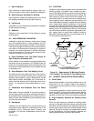
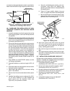
connected so that good electrical contact is provided be-
tween the shield and the high-frequency power source.
S-0021
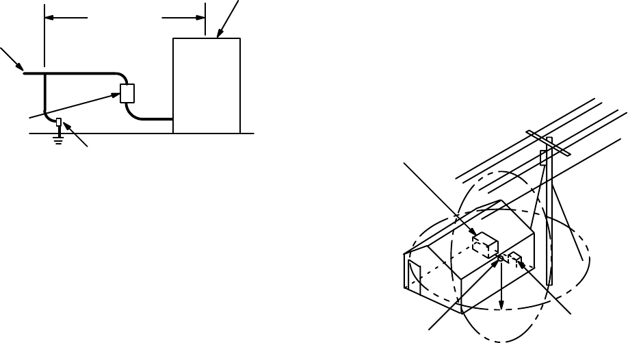
Line Input
50 ft. (15 m)
Power Supply
Solid Metallic Conduit
Line Fuse
And Switch
Ground
High-Frequency
Welding Power Source
Box
Figure 8-5. Installation Of High-Frequency
Stabilized Arc Welding Power Source
8-6. GUIDELINES FOR INSTALLATION OF HIGH-
FREQUENCY ASSISTED ARC WELDING POWER
SOURCES
1. Locate the equipment so that the ground wire of the
high-frequency power source can be kept as short
as possible.
2. Shield the line input power leads up to the point of
connection with the enclosure of the high-frequency
power source as specified by the manufacture’s re-
quirements (see Section 8-5F).
3. Be sure that there is good electrical contact made at
the enclosure of the high-frequency welding power
source, through the conduit, and back to the service
box. Be sure that the conduit system is continuous
to a point at least 50 ft. (15 m) from the equipment,
and that the conduit system is one complete run
within the high-frequency zone. If rigid, metallic con-
duit is not used, be sure that the shielding used has
equivalent shielding efficiency. Copper sleeving,
lead covered cable, or the equivalent, is satisfac-
tory. Spirally wound, flexible, metallic conduit is not
suitable.
4. Keep WORK and ELECTRODE cables as short
and straight as possible.
5. Keep weld cables to a maximum length of 25 ft. (8
m).
6. Keep weld cables as close together and as close to
the ground plane as possible.
7. Adjust spark gap setting to the minimum setting
given in this manual.
8. Secure all service and access doors before operat-
ing.
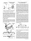
9. Visualize the welding zone as a sphere with a 50 ft.
(15 m) radius centered on a point between the
power source and the electrode holder (see
Figure 8-6), and proceed as follows:
a. Have all unshielded power, lighting, and com-
munication wires within the welding zone
placed in grounded shields or relocated outside
the welding zone.
b. Ground all large metallic objects, long guy
wires, or support wires within the welding zone.
c. Be sure that there are no external power or tele-
phone wires, which may be off the immediate
premises, within the welding zone.
S-0022
Center Point
High-Frequency
Welding Power
Source
Electrode
Holder
Figure 8-6. Welding Zone
10. Use driven ground rods which enter the ground
10 ft. (3 m) or less from the ground connection, or
cold water pipes, as the ground for the high-fre-
quency welding power source.
11. Be sure that all ground connections are clean and
tight.
12. If the high-frequency welding power source is oper-
ated within a metal building, be sure that the building
is properly grounded.
8-7. INSTALLATION GUIDELINES CHECKLIST
All items may not be necessary or practical for each in-
stallation. Complete the necessary items to eliminate in-
terference with authorized FCC services.
1. Is equipment properly located?
(See Sections 8-4, 8-5D, 8-5E, 8-6.1, and 8-6.9.)
2. Are ac input power connections properly made?
(See Sections 8-5B, 8-6.2, and 8-6.3.)
3. Are weld cables and equipment properly installed?
(See Sections 8-5A, 8-6.4, 8-6.5, and 8-6.6.)
4. Are ground connections properly made?
(See Sections 8-5C, 8-6.1, 8-6.6, 8-6.11, and
8-6.12.)
5. Is equipment properly set up and adjusted?
(See Sections 8-6.7 and 8-6.8.)