


OM-533 Page 3
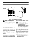
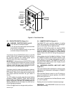
ST-113 509-A
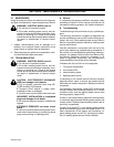
Mounting
Screws (5)
Front
Panel
Cover
Dip
Switch
Circuit
Board
PC5
Both dip switches down for
1000 ampere model operation
Both dip switches up for
650 ampere model operation
Figure 2-2. Dip Switch Positions And Locations
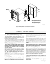
SECTION 3 – OPERATOR CONTROLS
3-1. MODE
SELECT
OR SWITCH (Figure 3-1)
The Mode Selector switch allows selection of CC
(constant
current), CV (constant voltage),
or pulsed out
-
put from the welding power source.
The
CC position provides a constant current output spe
-
cifically designed for Shielded Metal Arc (SMAW) and
Gas
T
ungsten Arc (GT
A
W) W
elding processes. The CC
position
is also normally used for Air Carbon Arc Cutting
(CAC-A) and gouging processes.
The
CV position provides a constant voltage output de
-
signed
for wire feeding applications such as Gas Metal
Arc (GMAW), Flux Cored Arc (FCAW), or Submerged
Arc
(SA
W) Welding.
When
pulsed output is desired for Gas Metal Arc W
eld-
ing
- Pulsed Arc (GMA
W
-P), place switch at the desired
number of pulses per second: 60, 90, 120 or 180.
3-2. ARC
CONTROL AND PILOT LIGHT
(Figure 3-1)
IMPORTANT:
The ARC CONTROL potentiometer and
pilot
light are disabled in the CV (Constant V
oltage) and
pulsed modes.
The ARC CONTROL potentiometer provides variable
selection of short-circuit current to suit individual weld-
ing conditions. Rotating this control clockwise causes
the current to increase as the short-circuit condition is
approached. When this control is set at some value
above 0, the current begins to increase when arc volt-
age drops below 20 volts.
When the control is set at 10 (MAX.), the short-circuit
current
is considerably
higher than normal welding cur
-
rent (see welding power source volt-ampere curve for
CC
mode). This provides extra current for arc starting in
out-of-position
welds as well as for certain types of elec
-
trodes.
When
the control is set at 0 (SOFT), short-circuit current
is the same as normal welding current. The 0 position
provides
current characteristics associated
with the Gas
Tungsten Arc Welding (GTAW) process.
When the control is set at 5, short-circuit current is
approximately
half that of the 10 (MAX.) position but still
higher
than normal welding current. The 5 position pro
-
vides a moderate current increase for arc starting nec-
essary
for certain types of electrodes and
applications.
Select a setting best suited for the application.
The Arc Control pilot light turns on when the Mode Se-
lector
switch is in the CC position indicating that the ARC
CONTROL is active.
IMPORTANT:
The ARC CONTROL can be adjusted
while welding.