


OM-533 Page 4
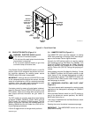
ST-109 521-A
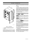
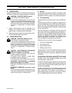
Voltmeter
Ammeter
Volts/Peak
Control And
Pilot Light
Amps/Bkgd
Control And
Pilot Light
Mode
Selector
Switch
Ammeter
Switch
Arc
Control
Arc Control
Pilot Light
Contactor
Switch
Figure 3-1. Front Panel View
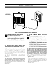
3-3. CONTACTOR SWITCH (Figure 3-1)
WARNING: ELECTRIC SHOCK can kill.
•
Do not touch live electrical parts.
•
Do
not touch the weld output terminals when
the contactor is energized.
•
Do not touch electrode holder (or gun wire)
and work clamp at the same time.
If
the Remote
Control CONT
ACT
OR switch is in the ON
position,
open-circuit voltage will be present at the out
-
put terminals whenever the welding power source
POWER switch ON button is depressed.
IMPORTANT:
Although the term CONT
ACT
OR is used
on
the nameplate and throughout this manual, the
weld
output is not switched on or off by a physical secondary
contactor;
rather
, the weld output is controlled by
solid-
state circuitry in the welding power source.
If
contactor control by means of
a wire feeder is desired,
place the Remote Control CONTACTOR switch in the
OFF
position. Open-circuit voltage will be present at the
weld output terminals whenever the gun switch is
closed.
The
OFF position is normally used with all wire feeding
processes (GMAW, GMAW-P, FCAW, SAW) and the
Gas Tungsten Arc Welding (GTAW) process. The ON
position is normally used with the Shielded Metal Arc
Welding
(SMA
W) and the Air Carbon Arc (CAC-A)
Cut
-
ting and gouging processes.
Lift end of toggle switch to change switch positions.
3-4. AMMETER SWITCH (Figure 3-1)
The AMMETER switch provides selection of reading
PEAK weld amperage or Average (AVG) weld amper-
age on the Remote Control digital ammeter.
Normally the AVG switch position is used for reading
weld amperage during Gas Metal Arc (GMAW), Flux
Cored Arc (FCAW), Submerged Arc (SAW), Shielded
Metal
Arc (SMA
W), Gas T
ungsten Arc (GT
A
W) W
elding
and Air Carbon Arc (CAC-A) Cutting and gouging pro-
cesses.
While
welding using the Gas
Metal Arc W
elding - Pulsed
Arc (GMA
W
-P) process, the A
VG switch position is
used
when display of the average (background and peak)
weld amperage is desired. The AMMETER switch can
be placed in the PEAK position when display of peak
weld amperage is desired.
3-5. AMPS/BKGD CONTROL AND PILOT LIGHT
(Figure 3-1)
This
control presets weld amperage for constant current
applications and background amperage for GMAW-P
applications.
When
the Mode Selector switch is in the
CC position or
one of the pulses per second positions, the AMPS/
BKGD pilot light turns on.
This
control is disabled
when the Mode Selector switch
is in the CV position.
Rotating the control clockwise increases amperage.
IMPORTANT:
The AMPS/BKGD control can be ad-
justed while welding.