


. Complete Parts List available at www.MillerWelds.com
OM-4415 Page 17
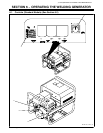
SECTION 5 − INSTALLATION
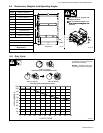
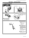
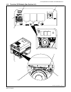
5-1. Installing Welding Generator
Ref 151 556 / Ref. 800 652 / 803 597-B / S-0854
18 in
(460 mm)
18 in
(460 mm)
18 in
(460 mm)
18 in
(460 mm)
18 in
(460 mm)
OR
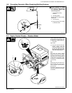
Movement Airflow Clearance
Location
Do not install unit where air
flow is restricted or engine
may overheat.
Always securely fasten welding
generator onto transport vehicle
or trailer and comply with all
DOT and other applicable codes
GND/PE
2
3
1
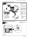
Always ground generator frame
to vehicle frame to prevent elec-
tric shock and static electricity
hazards.
1 Metal Vehicle Frame
2 Equipment Grounding
Terminal
3 Grounding Cable
Bed liners, shipping skids, and
some running gear insulate the
welding generator from the ve-
hicle frame. Always connect a
ground wire from the generator
equipment grounding terminal
to bare metal on the vehicle
frame as shown.
Use #10 AWG or larger insulated
copper wire to make metal-to-met-
al grounding connection.
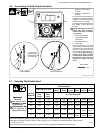
If unit does not have GFCI
receptacles, use GFCI-
protected extension cord.