


. Complete Parts List available at www.MillerWelds.com
OM-4415 Page 20
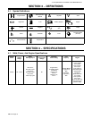
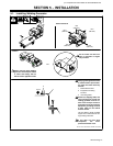
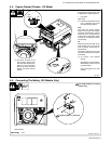
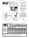
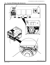
5-6. Connecting To Weld Output Terminals
803 596−B / 803 778-A
1 Positive (+) Weld Output
Terminal
2 Negative (−) Weld Output
Terminal
For Direct Current Electrode Posi-
tive (DCEP), connect work cable to
Negative (−) terminal and electrode
holder to Positive (+) terminal.
For Direct Current Electrode nega-
tive (DCEN), reverse cable con-
nections.
Tools Needed:
3/4 in
6
4
5
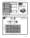
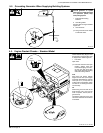
Do not place
anything between
Correct Installation Incorrect Installation
3
weld cable terminal
and copper bar.
1
2
Failure to properly connect weld
cables may cause excessive
heat and start a fire, or damage
your machine.
3 Weld Output Terminal
4 Supplied Weld Output
Terminal Nut
5 Weld Cable Terminal
6 Copper Bar
Remove supplied nut from weld
output terminal. Slide weld cable
terminal onto weld output terminal
and secure with nut so that weld
cable terminal is tight against cop-
per bar. Do not place anything
between weld cable terminal
and copper bar. Make sure that
the surfaces of the weld cable
terminal and copper bar are
clean.
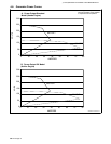
5-7. Selecting Weld Cable Sizes*
Weld Cable Size** and Total Cable (Copper) Length in Weld Circuit
Not Exceeding***
100 ft (30 m) or Less
150 ft
(45 m)
200 ft
(60 m)
250 ft
(70 m)
300 ft
(90 m)
350 ft
(105 m)
400 ft
(120 m)
Weld O tp t
Welding
Amperes
10 − 60%
Duty
Cycle
60 − 100%
Duty
Cycle
10 − 100% Duty Cycle
Weld Output
Terminals
100 4 (20) 4 (20) 4 (20) 3 (30) 2 (35) 1 (50) 1/0 (60) 1/0 (60)
Stop engine before
connectin
g
to weld
150 3 (30) 3 (30) 2 (35) 1 (50) 1/0 (60) 2/0 (70) 3/0 (95) 3/0 (95)
connecting to weld
output terminals.
Do not use worn dam-
200 3 (30) 2 (35) 1 (50) 1/0 (60) 2/0 (70) 3/0 (95) 4/0 (120) 4/0 (120)
D
o
no
t
use
worn,
d
am-
aged, undersized, or
poorly spliced cables.
250 2 (35) 1 (50) 1/0 (60) 2/0 (70) 3/0 (95) 4/0 (120)
2 ea. 2/0
(2x70)
2 ea. 2/0
(2x70)
300 1 (50) 1/0 (60) 2/0 (70) 3/0 (95) 4/0 (120)
2 ea. 2/0
(2x70)
2 ea. 3/0
(2x95)
2 ea. 3/0
(2x95)
* This chart is a general guideline and may not suit all applications. If cables overheat, use next size larger cable.
**Weld cable size (AWG) is based on either a 4 volts or less drop or a current density of at least 300 circular mils per ampere.
( ) = mm
2
for metric use S-0007-F
***For distances longer than those shown in this guide, call a factory applications representative at 920-735-4505.