


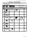
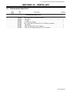

. Complete Parts List available at www.MillerWelds.com
OM-4415 Page 26
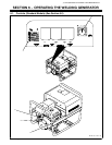
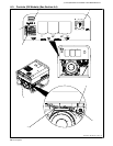
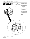
SECTION 7 − OPERATING AUXILIARY EQUIPMENT
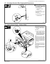
. Generator power decreases as weld
current increases. Set Weld Output
control to maximum for full generator
power output at AC receptacles.
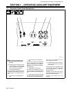
1 240 V AC Receptacle RC1
RC1 supplies 60 Hz single-phase power at
weld/power speed. Maximum output is 6
kVA/kW (peak) or 5.5 kVA/kW (continu-
ous).
2 120 V 20 A AC Duplex Receptacle
RC2
3 120 V 20 A AC Duplex Receptacle
RC3
RC2 and RC3 supply 60 Hz single-phase
power at weld/power speed. Maximum
output from RC2 or RC3 is 2.4 kVA/kW.
NOTICE − Do not parallel the two 120V du-
plex receptacles.
4 Supplementary Protector CB1
CB1 protects the receptacles from over-
load. If CB1 opens, the receptacles do not
work. Move switch to the On position to re-
set.
5 Supplementary Protectors CB2, CB3
CB2 protects RC2 and CB3 protects RC3
from overload. If the supplementary pro-
tector opens, the receptacle does not
work. Press button to reset.
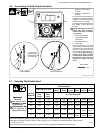
. If supplementary protector continues
to open, contact Factory Authorized
Service Agent.
Combined output of all receptacles limited
to 5.5 kVA/kW continuous rating of the
generator (See Section 12 − Generator
Power Guidelines).
EXAMPLE: If 10 A is drawn from each 120
volt duplex receptacle, only 13 A is avail-
able from the 240 V receptacle.
2 x (120 V x 10 A) + (240 V x 13 A) = 5.5
kVA/KW.
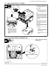
7-1. Generator Power Panel Receptacles
218 611−B
124 35
If unit does not have GFCI recep-
tacles, use GFCI-protected exten-
sion cord.