


OM-223 839 Page 11
SECTION 4 − OPERATION
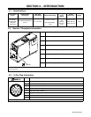
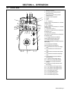
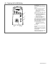
4-1. Control Panel
1 MIG Gun Connector
2 Red Quick Connect Fitting (Coolant
Return From Gun).
3 Blue Quick Connect Fitting (Coolant
Output To Torch)
4 Remote Control Receptacle
5 Handle
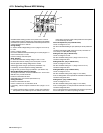
6 Panel
7 D1 − (Display 1)
Displays values and parameters for selected
welding process.
8 D2 − (Display 2)
Displays values and parameters for selected
welding process.
9 E1 (Encoder Control 1)
Use control to change values and parameters
that appear on D1.
10 E2 (Encoder Control 2)
Use control to change values and parameters
that appear on D2.
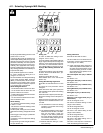
11 P1 (Trigger Selection Push Button)
Allows selecting desired trigger mode.
12 P2 (Memory/Setup Push Button)
Allows selecting Memory and Setup menus for
MIG welding.
13 P8 (Jog/Purge Push Button)
Performs jog and purge operations.
14 L1 ON means that D1 shows the voltage
value
15 L2 ON means that D1 shows the Trim
value
16 L3 ON means that D2 shows Wire Speed
value
17 L4 ON means that D2 shows Amperage
value
18 L5 ON means that D2 shows Material
Thickness value
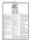
19 L6 selection is Manual MIG welding
20 L7 selection is Synergic MIG welding
21 L8 selection is Synergic Pulsed MIG
welding
22 L9 selection is Synergic Double Pulsed
MIG welding
23 L10 ON selects 2 times trigger function
24 L11 ON selects 4 times trigger function
25 L12 ON selects 3 levels trigger function
26 L13 ON selects Setup menu
27 L14 On selects Memory menu
28 L15 ON selects Jog function
29 L16 ON selects Purge function
1
2
3
4
29
10
28
16 17 18
6
587
9
19
20
21
22
15
14
23
24
25
26
12 13
27
11