


OM-2254 Page 27
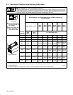
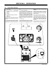
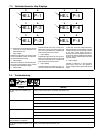
7-3. Voltmeter/Ammeter Help Displays
. All directions are in reference to the front
of the unit. All circuitry referred to is lo-
cated inside the unit.
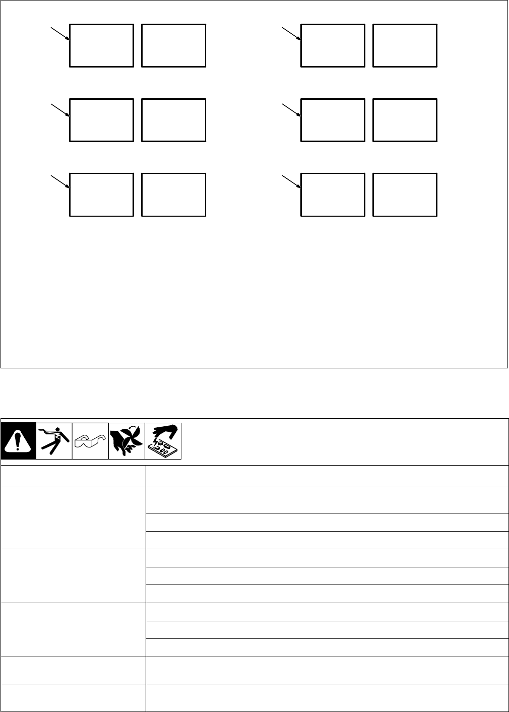
1 Help 1 Display
Indicates a malfunction in the primary power
circuit. If this display is shown, contact a Fac-
tory Authorized Service Agent.
2 Help 2 Display
Indicates a malfunction in the thermal protec-
tion circuitry. If this display is shown, contact
a Factory Authorized Service Agent.
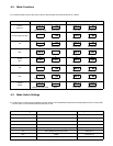
3 Help 3 Display
Indicates the left side of the unit has over-
heated. The unit has shut down to allow the
fan to cool it (see Section 4-3). Operation will
continue when the unit has cooled.
4 Help 5 Display
Indicates the right side of the unit has over-
heated. The unit has shut down to allow the
fan to cool it (see Section 4-3). Operation will
continue when the unit has cooled.
5 Help 6 Display
Indicates operation at maximum input cur-
rent. The unit has a maximum allowable input
current limit. As the line voltage decreases,
the required input current increases. If the line
voltage is too low, the output power is limited
by the input current. When this limit is
reached, the unit automatically reduces out-
put power to continue operation. If this display
is shown, have a qualified electrician check
the input voltage.
6 Help 8 Display
Indicates a malfunction in the secondary
power circuit of the unit. If this display is
shown, contact a Factory Authorized Service
Agent.
1
AV
2
AV
HE.L P−1
HE.L P−2
3
AV
HE.L P−3
4
AV
5
AV
HE.L P−5
HE.L P−6
6
AV
HE.L P−8
7-4. Troubleshooting
Trouble Remedy
No weld output; unit completely inop-
erative.
Place line disconnect switch in On position (see Section 5-2).
Check and replace line fuse(s), if necessary, or reset circuit breaker (see Section 5-2).
Check for proper input power connections (see Section 5-2).
No weld output; meter display On. Input voltage outside acceptable range of variation (see Sections 5-2, 5-3).
Check, repair, or replace remote control.
Unit overheated. Allow unit to cool with fan On (see Section 4-3).
Erratic or improper weld output. Use proper size and type of weld cable (see Section 5-4).
Clean and tighten all weld connections.
Check for correct polarity.
No 115 volts ac output at duplex recep-
tacle or Remote 14 receptacle.
Reset circuit breaker CB1 (see Section 5-6).
No 24 volts ac output at Remote 14 re-
ceptacle.
Reset circuit breaker CB2 (see Section 5-6).