


8 9
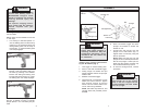
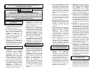
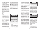
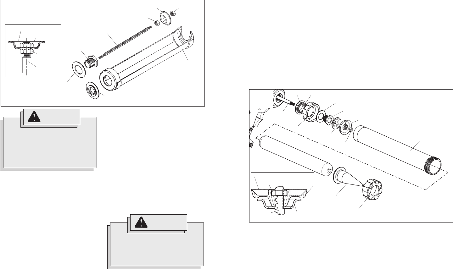
Installing Barrel Assembly (Cat. No.
6560-24) (Fig.5)
1. Lock trigger or remove battery pack.
2. Press in and hold rod release trigger.
3. Grasp plunger rod handle and pull
plunger rod back until the rod tip is just
inside of tool.
4. Release rod release trigger.
5. Position spacer and back cap (fine
threads) onto nose of the tool as
shown (Fig. 5). The side of the spacer
with the double hub fits inside the back
cap.
6. Place backing washer on top of back
cap and thread barrel nut into nose of
the tool as shown (Fig. 5). Tighten nut
using the spanner end of the wrench
provided with the tool.
7. Press rod release trigger and push
plunger rod forward to access the
threads on rod.
8. Thread plunger, barrel plunger and nut
onto the plunger rod in order shown
(Fig. 5).
9. Thread barrel tube into back cap.
10. To remove barrel tube, reverse proce-
dure.
Installing Caulk or Adhesive Tube
1. Lock trigger or remove battery pack.
2. Cut nozzle of tube at an angle and
size per manufacturer's recommenda-
tion to suit the job. A smaller nozzle
diameter requires more force to push
the caulk and reduces battery life.
3. Break inner seal of tube using a long
nail or piece of wire. If the inner seal
is not broken, the caulk material may
be forced out the rear end of the tube
and damage the tool.
NOTE: Before using a partially filled
tube, remove any hardened material
with a long nail or piece of wire.
4. Press in and hold rod release trigger.
5. Grasp plunger rod handle and pull
plunger rod back to allow the caulk
tube to fit inside carriage frame.
6. Insert caulk tube into carriage frame.
7. Push plunger rod handle forward until
the plunger is against the caulk tube.
8. Release rod release trigger.
Plunger
rod
Plunger
Backing washer
Back cap
Barrel
Spacer
Barrel plunger
Barrel nut
Nut
Nozzle cap
Nozzle
Double hub
Front face of plunger
Barrel
plunger
Plunger
Plunger
rod
Nut
Fig. 5
6560-24
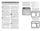
WARNING!
Always lock trigger or remove
battery pack before changing or
removing accessories. Only use
accessories specifically recom-
mended for this tool. Others may
be hazardous.
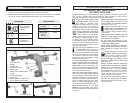
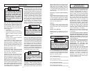
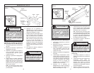
Installing 30oz Carriage Frame
Assembly (Cat. No. 6560-23) (Fig. 4)
1. Lock trigger or remove battery pack.
2. Press in and hold rod release trigger.
3. Grasp plunger rod handle and pull
plunger rod back until the rod tip is just
inside of tool.
4. Release rod release trigger.
5. Insert spacer into front face of tool
body. The side with the larger diam-
eter hub fits inside the tool. Place car-
riage frame over washer. Assemble
backing washer and barrel nut to tool
as shown (Fig. 4). Tighten Barrel nut
with wrench provided.
WARNING!
To reduce the risk of injury,
keep hands out of the plunger
area of the tool. Fingers can be
pinched between the tube holder
and the plunger.
Fig. 4
Plunger
Plunger rod
Nut
Carriage frame
Barrel nut
Nut
Backing
Washer
6. Press rod release trigger and push
plunger rod forward to access the
threads on rod.
7. Thread nuts and plunger onto the
plunger rod in order shown (Fig. 4).
Tighten back nut securely using the
wrench provided.
NOTE: Make sure the front nut and
plunger rod do not extend past the front
face of the plunger. If either part ex-
tends past the plunger, the back cap
of the material tube may rupture.
8. To remove carriage frame, reverse
procedure.
6560-23
Front face of plunger
Front nut
Back nut
Plunger rod
Spacer