


6.1 Standard specification
SPECIFICATIONS
41
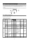
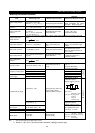
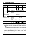
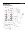
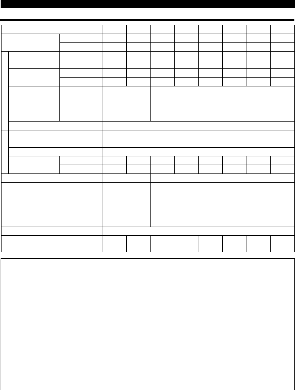
6.1.1 Model specifications
Model FR-A560L- K-NA
375 450 530 600 670 750 800 900K
Constant torque 375 450 530 600 670 750 800 900Applicable motor
capacity (kW)
(Note 1)
Variable torque 450 530 600 670 750 800 900 950
Constant torque 550 650 750 800 900 1000 1100 1200Rated capacity (HP)
(Note 2)
Variable torque 650 750 800 900 1000 1100 1200 1300
Constant torque 552 663 773 800 880 990 1100 1210
Rated current (A)
Variable torque 663 773 800 880 990 1100 1210 1320
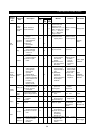
Constant torque
150% 60 sec., 200%
0.5 sec (inverse-time
characteristics)
150% 60 sec. (inverse-time characteristics)
Overload capacity
Variable torque
120% 60 sec., 150%
0.5 sec (inverse-time
characteristics)
120% 60 sec. (inverse-time characteristics)
Output
Voltage Three phase, 575V 50 60Hz
Rated input AC voltage, frequency
Three phase, 575V 50 60Hz
Tolerable AC voltage fluctuation
488 to 632V 50 60Hz
Tolerable frequency fluctuation
5%
Constant torque 550 660 770 797 896 986 1095 1205
Power supply
Power facility
capacity (kVA)
Variable torque 660 770 797 896 986 1095 1205 1315
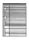
Protective structure (JEM 1030) Open type (IP00) Open type (IP20)
Ambient temperature
-10
°
C to 40
°
C
(14
°
F to 104
°
F) at
VT
-10
°
C to 50
°
C
(14
°
F to 122
°
F) at
CT
-10
°
C to 40
°
C (14
°
F to 104
°
F)
Cooling method
Forced air cooling
Approx. weight (kg (lb) )
490
(1078)
500
(1100)
1060
(2332)
1060
(2332)
1100
(2420)
1100
(2420)
1200
(2640)
1200
(2640)
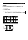
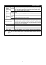
Note: 1. The applicable motor capacity indicated is the maximum capacity applicable when Mitsubishi 4-pole
standard motor is used For A540K. (When National Electric Code based motor is used for A560L)
2. The rated output capacity indicated is based on National Electric Code for 460V for A540L. (575V for
A560L)
3. The overload capacity indicated in % is the ratio of the overload current to the inverter’s rated current.
For repeated duty, allow time for the inverter and motor to return to or below the temperatures under
100% load.
4. The maximum output voltage cannot exceed the power supply voltage. The maximum output voltage
may be set as desired below the power supply voltage.
5. The power supply capacity changes with the values of the power supply side inverter impedance
(including those of the input reactor and cables).
6. For use in Variable torque mode, refer to Pr. 570.
7. For inverter environmental conditions (including ambient temperature) please check page A-3.