


Appendix 4
APPENDICES
49
Appendix 4
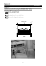
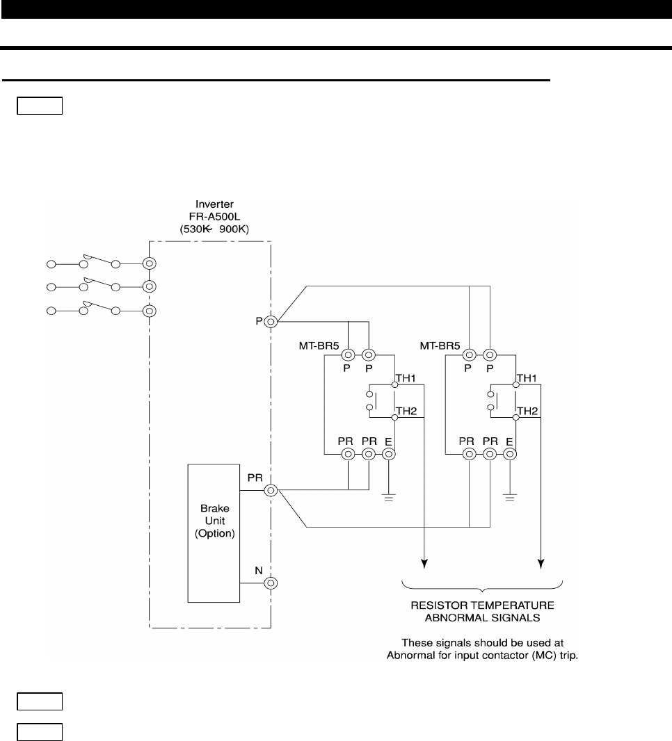
Installation procedure for brake unit (option) (FR-A560L-530K 900K)
Step1
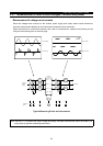
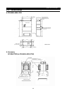
Connect wires as the next drawing.
Wiring between FR-A500L and MT-BR5 (option)
Step2
Set parameter 30 : when brake unit is used, set to 1.
Step3
Set parameter 70 : when brake unit is used, set to 10%.
This brake unit and brake resistor are designed at 10%.