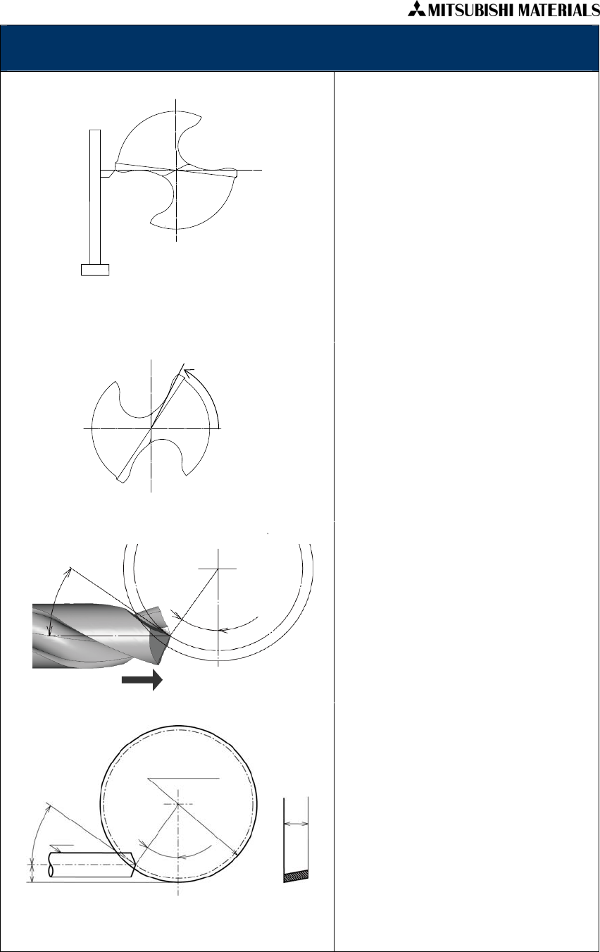
Grinding thinning face
• After grinding second relief face, grind
thinning face. Type of the thinning is
X-thinning.
• First, set the work head horizontal so that
the center of the drill will be horizontal.
Drill rotation angle is 0°. Set the direction
of table oscillation parallel with the center
line of the drill.
• As shown in fig.7, set the drill phase so
that the line connecting the shoulder of
both sides will be horizontal by using a
device such as height gage.
• Then, as shown in fig.8, rotate the drill
counter clockwise 65°when seen from the
top.
• Set the vertical position of the wheel so
that the open angle of the thinning from
the drill center will be 35°, as shown in
fig.9.
• As shown in fig.10, set the wheel height
so that the center line of the drill will be
higher than the bottom of the the wheel
edge by “L”. (Please refer to the formula
in figure 10.)
• As shown in fig.9, grind the thinning face
by sliding the table to the direction shown
by the arrowhead, pressing the drill
against the wheel. Grind slowly adjusting
the top end of cut by using a device such
as a stopper.
Height gage
Fig.7
Fig.8
65°
Fig.9
35°
35°
Cutting direction
L=0.5×φD1×(1-cosθ)+H×tan10°×cosθ
Fig.10
θ
L
Drill
H
35°
Max. wheel diameter φD1
Copyright © 2009 MITSUBISHI MATERIALS CORPORATION. All rights reserved


