


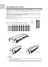
Installation of remote controller
27
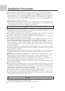
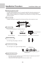
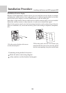
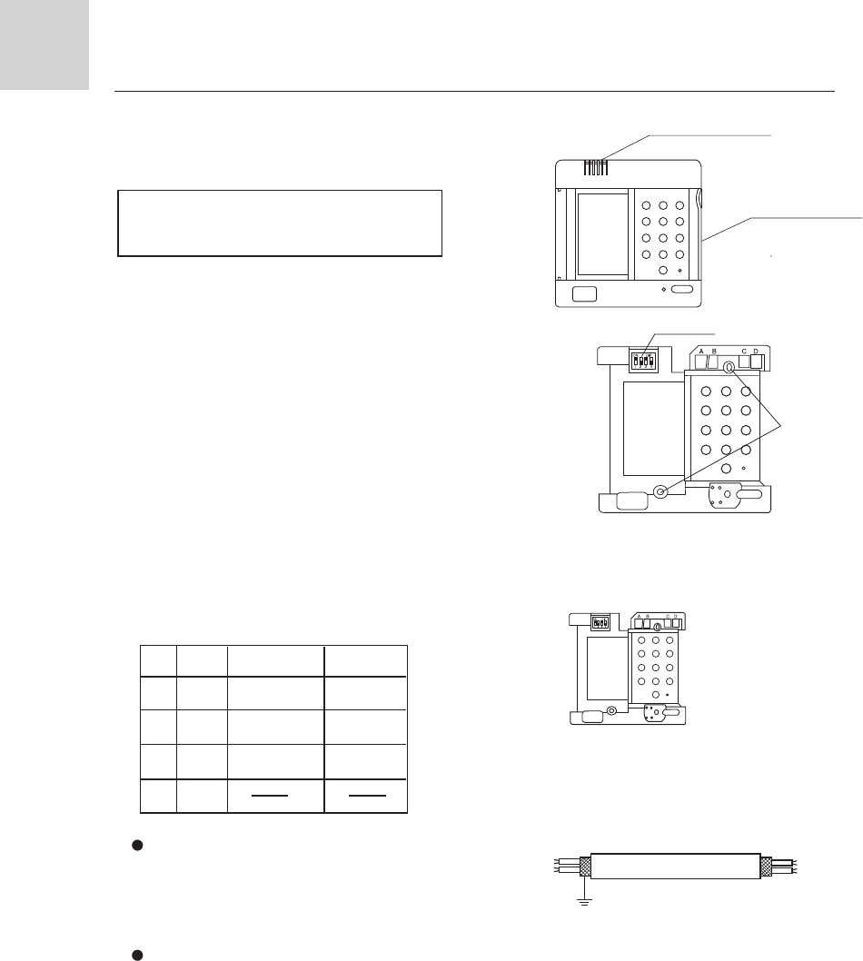
5. Replace the upper cover of wire controller
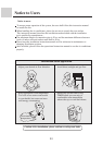
Note
Try as far as possible a flat surface for installation.
Don't use excessive force when tightening screws,
or lower part might got deformed.
PCB is mounted on lower part of wire
controller, be careful not to damage it.
Hint
1. Power supply switch and signal wire should be prepaired by the user.
2. Don't touch PCB with hand.
Be careful not to hold down the wiring.
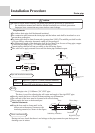
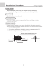
1. Remove upper cover of wire controller
Remove upper part of wire controller
by press.
Lower cover of wire
controller
Upper cover of wire
controller
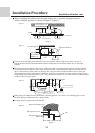
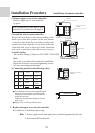
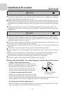
2. Install the wired remote controller
Please drill two holes on the wall according to the
back cover screw hole position of the wire remote
controller, then strike the wood block to the holes
respectively, then align the 2 screw hole of the wire
controller back cover to the wood block, fasten the
wire reote controller to the wall use wood screws.
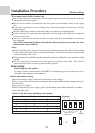
3. Switch setting
The switchs setting as follows:1.ON 2.OFF 3.ON 4.OFF
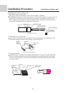
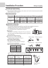
4. Connecting method as the following chart
Switch button
Screw hole
Back cover of the wire
controller
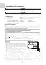
Installation Procedure
Use shielede wires for telecommunication
between wire controller and indoor unit;
indoor unit and outdoor unit. Ground the
shield on one side.
Otherwise misoperation because of noise
may occur.
Signal wire is self-provided by user.
Shielded wire
ground
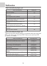
No
Symbol
colour
contents
1
2
3
4
A
B
C
D
White or Green
Red
Yellow
COM
Gnd
12V