


EHTX44Y5 RIDE-ON TROWEL • OPERATION MANUAL — REV. #0 (01/16/13) — PAGE 17
CONTROLS AND INDICATORS
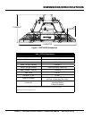
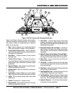
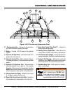
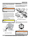
Figure 2. EHTX Controls and Components (Front)
9
8
5
7
6
2
4
3
1
13
15
14
18
16
19
12
12
17
11
10
10
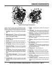
EHTX
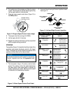
Figure 2 and Figure 3 show the location of the controls,
indicators and general maintenance parts. The function of
each control, indicator or maintenance part is explained
below and on next page.
1. Seat – Place for operator to sit. Trowel blades will not
rotate unless operator is seated. Seat is adjustable.
2. Trowel Speed Limiter Control – Used to adjust the
maximum trowel speed that can be obtained when the
foot pedal is fully depressed.
3. Hour Meter – Indicates number of hours machine
has been used.
4. Throttle Control Lever – Controls the speed of
the engine. Move the hand lever forward to increase
engine speed (high), backwards to decrease engine
speed (low).
5. Operator Gauges – Allows operator to monitor engine,
hydraulic and electrical functions.
6. Ignition Switch – With key inserted turn clockwise to
start engine.
7. Light Switch – When activated, turns on six halogen
lights. Lights offer better visibility when working indoors.
8. Lights – Six low voltage halogen lights are provided
with this unit.
9. Toolbox Compartment – Storage for tools.
10. Spray Nozzles – Spray nozzle for retardant. Two spray
nozzles are supplied with this unit.
11. Foot Pedal – Controls blade speed. Slow blade
speed is accomplished by slightly depressing the foot
pedal. Maximum blade speed is accomplished by fully
depressing the foot pedal.
12. Removable Steps (Left and Right) – Provides for
safe footing for mounting and dismounting trowel.
When removed, provides access to spider and blade
assemblies.
13. Retardant Spray Control Buttons (Left and Right) –
When pressed allows retardant spray to flow through
the spray nozzle located at the front of the machine.
14. Hand Grip – Use to assist safe mounting and
dismounting of trowel.
15. Lift Loops – Located on both the left and right sides
of the main frame. Used when the trowel must be lifted
onto a concrete slab.
16. Pitch Block – (Behind grill guard.) Measure and adjust
pitch pressure at the pitch block.
17. Fuel Gauge/Filler Cap – Indicates the amount of fuel
in the fuel tank. Remove this cap to add fuel.
18. Overflow Bottle – (Behind grill guard.) Supplies water
or coolant to the radiator when radiator water or coolant
level is low. Fill to indicated level as shown on bottle.
19. Hydraulic Reservoir – Part of frame. Holds hydraulic
oil necessary for pump operation.