


EHTX44Y5 RIDE-ON TROWEL • OPERATION MANUAL — REV. #0 (01/16/13) — PAGE 35
MAINTENANCE
TROWEL ARM ADJUSTMENT
Use the following procedure to check and adjust trowel
arms, and check for worn or damaged components when
it becomes apparent that the trowel is finishing poorly or
in need of routine maintenance.
Look for the following indications. Trowel arm alignment,
worn spider bushings or bent trowel arms may the cause.
Are blades wearing unevenly? Is one blade completely
worn out while the others look new?
Does the machine have a perceptible rolling or bouncing
motion when in use?
Look at the machine while it is running; do the guard
rings “rock up and down” relative to the ground?
1. Place the trowel on a FLAT, LEVEL surface.
2. A level, clean surface area to test the trowel prior to
and after is essential. Any unlevel spots in the floor or
debris under the trowel blades will give an incorrect
perception of adjustment. Ideally, a 5 x 5 ft. (1.5 x 1.5
m) three-quarter inch (19 mm) thick FLAT steel plate
should be used for testing.
3. Pitch the blades as flat as possible. The adjustment
bolts should all barely make contact with the lower
wear plate on the spider. If one is not making contact,
adjustment will be necessary.
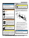
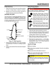
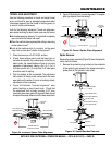
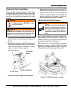
4. Figure 34 illustrates, "incorrect alignment", worn
spider bushings or bent trowel arms. Check that
the adjustment bolt is barely touching (0.10" max.
clearance) lower wear plate. All alignment bolts should
be spaced the same distance from the lower wear plate.
Figure 34. Incorrect Spider Plate Alignment
Surface
Dished Effect on
Finished Concrete
Adjustment Bolt
NO
Adjustment Bolt
Lower Wear Plate
Hydraulic
Motor
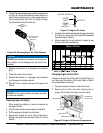
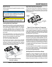
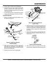
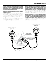
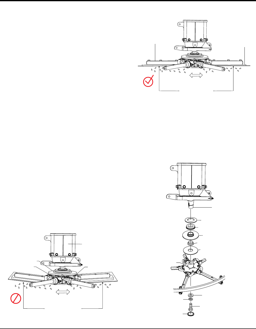
5. Figure 35 illustrates the "correct alignment " for a spider
plate (as shipped from the factory).
Figure 35. Correct Spider Plate Alignment
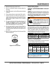
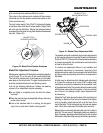
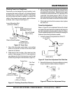
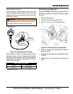
Spider Removal
Remove the spider assembly (Figure 36) from the hydraulic
motor shaft as follows:
1. Remove the protective plug located on the underside
of the spider to gain access to the screw securing the
spider plate to the hydraulic motor shaft.
Figure 36. Spider/Gearbox Removal
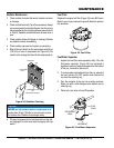
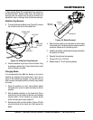
TROWELARM
BLADE
MOUNTING
BAR
Surface
Correct Alignment
Flat Flat
Upper Wear Plate
Thrust Collar Bearing
Thrust Collar
Thrust Collar Bushing
Lower Wear Plate
Hydraulic Motor
Shaft
Spider Plate
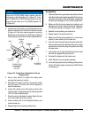
Retainer
Lock Washer
Retaining Screw
Plug