


GLW-180H A.C. GENERATOR/WELDER — PARTS & OPERATION MANUAL — REV. #5 (03/14/05) — PAGE 11
GLW-180H — INSTRUMENTATION
CAUTION :
When using a combination of dual
receptacles, total load should not exceed
the rated capacity of the generating.
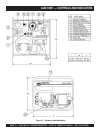
The definitions below describe the controls and functions of the
of the GLW-180 H Generator/Welder.
1. Ground Terminal Equipment – If required ground
equipment (power tools etc,) to this ground terminal. This
ground is not
EARTH
ground.
2. 120 VAC Twist Lock Receptacle – This unit is supplied
with one
Twist Lock
NEMA L5-30R (120V, 30 Amp)
output receptacle.
3. 120 VAC GFCI Receptacle – This unit is supplied with
one
Duplex
NEMA (GFCI) 5-20R (120V, 20 Amp) output
receptacle.
4. AC Voltmeter – This voltmeter indicates (with a mark) the
rated 60 Hz, 120 VAC
single phase output voltage
. In
addition the voltmeter can also be used as a diagnostic
tool.
If the voltmeter indicator (needle) is below the rated voltage,
engine problems may exist (low/high RPM's). To prevent
damage to the generator or power tools turn the generator
OFF and consult your authorized Multiquip service dealer.
5. Circuit Breaker – This single-pole, 40 amp breaker is
provided to protect both 120 VAC output receptacles from
overload.
6. Operation Switch – Must be in the up position (
ON
) for
normal operation. To turn-off generator place this switch in
the down position (
OFF
).
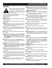
7. Current Regulator – Use this dial to adjust the welder's
output to the desired setting.
8. Idle Control Switch – This unit is provided with an
automatic idle control for noise suppression and reduced
fuel consumption. The automatic idle control automatically
enGLWges under a no-load condition.
With the automatic idle control switched “ON”, the engine
revolutions will automatically drop to about 2500 rpm (low-
speed operation) within 3 seconds after the load stops.
When the operation is resumed, the engine speed is
automatically increased to about 3600 rpm (high-speed
operation) as soon as the load is connected.
9. Current Regulator Selector Switch – Two position switch,
left
position selects minimum current output (min.-130
amps),
right
position selects maximum current output
(max.-180).
10. DC Output Terminals – Connect the welder's (+) and (-)
welding cables to these terminals.
11. Fuel Tank – The fuel GLWuge is located on the fuel tank
and allows easy monitoring of the fuel level.
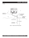
12. Chassis Ground – Connect earth ground (
ground
rod
)
to this lug. See Figure 3.
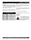
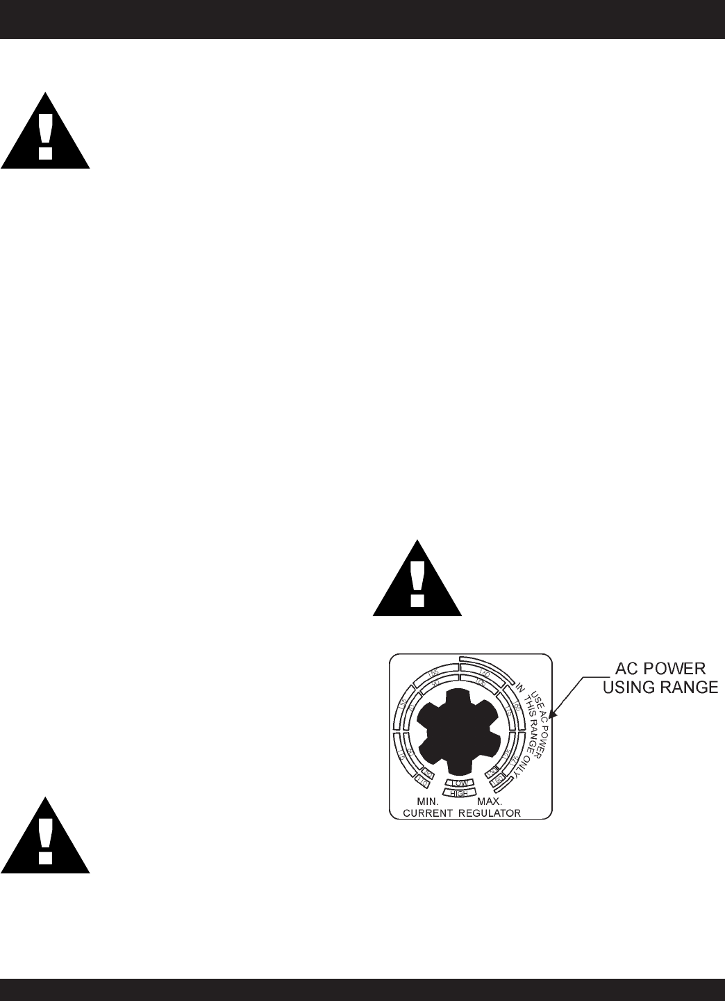
CAUTION :
When AC power is required, ALWAYS
place the current regulator dial in the
AC
power using range
.
NEVER turn the load ON or OFF by
connecting and disconnecting the load
power cord from the generator's AC output
receptacle. ALWAYS turn the circuit
breaker OFF to remove power from the
120 AC recepracles (load).
CAUTION :
Figure 2. Current Regulator Switch
AC Power Range