


PAGE 18 — GLW-180H A.C. GENERATOR/WELDER — PARTS & OPERATION MANUAL — REV. #5 (03/14/05)
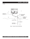
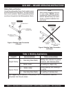
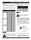
Welding Cables and Polarities
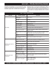
Connect the welding cables (Figure 4) to the welder's output
terminals located on the control panel. The output terminals
have (+) and (-) polarities. Select the appropriate polarities
according to the application (See Welding Application, Table 5).
Figure 4. Welding Cable Connection
(Correct)
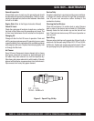
Figure 5. Welding Cable Connection
(Incorrect)
NOTE
Attach terminal connectors at the end
of each cable. NEVER connect
exposed wires (Figure 5) directly to the
terminal. Exposed wiring may cause
shocks or di-electric breakdown from
poor contact.
GLW-180H — WELDER OPERATING INSTRUCTIONS
snoitacilppAgnidleW.4elbaT
YTIRALOPDOHTEMGNIDLEWSNOITACILPPALACIPYT
ytiraloPthgiartS
)+(
...
)lateMesaB(gnidnuorG
larenegrofslairetamleetsgnidleW
.setalpssenkcihtdna,serutcurts
redloHredleW...)-(yol
lareppocrofgnidlewcrA
ytiraloPesreveR
redloHredleW...)+(
fognidlewCRA,gnidlewpu-dliuB
setalpniht
)+(
...
)lateMesaB(gnidnuorGleetssselniatsfognidlewcrA
ehtwollof,scitretcarahcVCehtniytiralopehtfonoitcelesehtg
nidraugeR:etoN
.rekameriwehtmorfsnoitcurtsni