


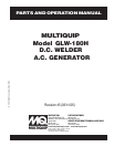


GLW-180H A.C. GENERATOR/WELDER — PARTS & OPERATION MANUAL — REV. #5 (03/14/05) — PAGE 9
GLW-180H — GENERAL INFORMATION
GLW-180H FAMILIARIZATION
Generator/Welder
The Multiquip Model GLW-180H generator has been designed
as a portable lightweight power source for 60 Hz (single-
phase) vibrators, lighting facilities, power tools, submersible
pumps and other industrial and construction machinery.
This generator is powered by a HONDA GLWsoline engine.
The alternator, a brushless revolving-field type, is
permanently aligned to the engine through rigid coupling.
The generator is mounted on rubber vibration isolators that
have a steel base backplate which is attached to the
protective steel pipe carrying frame. The protective carrying
frame is made of steel tubing and fully wraps around the
generator to protect aGLWinst damage.
This portable generator is supplied with a electrical
control
box
. To reduce vibration caused by the engine, the control
box is also placed on rubber isolators.
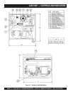
Control Box
The control box has the following: (all outputs are 60 Hz,
single phase)
z
One 120V output receptacle.
z
One 120V output receptacle (GFCI protected).
z
One main 40 amp circuit breaker.
z
AC Voltmeter
z
Idle Control Switch
z
Operation Switch
z
Output Terminals (Welding)
Excitation System
All GLW-series generators use a magnet attached to a
flywheel to produce AC voltage from a lamp coil beneath
the flywheel. As the magnet passes the coil it produces
approximately 19-22 AC volts.
This voltage (19-22 VAC) is then sent to the control box that
contains three rectifying diodes:
z
Excitation (diode 1)
z
Battery (diode 2)
z
Slow Down (diode 3)
The AC voltage will pass through the excitation diode that
converts the voltage to DC power.
This DC power is then sent to the excitation windings housed
within the main windings commonly called the "stator".
This voltage is then transferred into the rotor through
induction. The rotor contains two diodes within it which rectify
the DC voltage and send it out through the main windings,
as AC voltage.
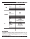
Engine
The four-cycle air-cooled HONDA GLWsoline engine is
designed to meet every performance requirement of this
generator. Reference Table 1, page 8 for engine
specifications.
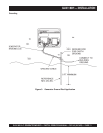
Figure 1 (page 10) shows the basic controls and indicators
for the GLW-180H generator.
Idle Control Switch
DO NOT use the idle control switch in conjunction with AC
electro-magnetic switches relays etc. Using the idle control switch
with these devices will cause the idle control device not to actuate.
If any of these devices are being used, leave the idle control
switch in the
OFF
position.
When running capacitor start motors such as submersible
pumps, the idle control switch should
NOT BE USED.
Disconnect the pump or tool from the power source by
switching OFF the main circuit breaker.
WARNING:
Before connecting this generator to
any building’s electrical system, a
licensed electrician must install an
isolation (transfer) switch.
Serious injury or death may result
without this transfer switch.
NOTE
In keeping with Multiquip's policy of
constantly improving its products, the
specifications quoted herein are subject
to change without prior notice.