PAGE 14 — GLW-180H A.C. GENERATOR/WELDER — PARTS & OPERATION MANUAL — REV. #5 (03/14/05)
General Inspection Prior to Operation
This generator has been thoroughly inspected and accepted
prior to shipment from the factory. However, be sure to check
for damaged parts or components, or loose nuts and bolts,
which could have occurred in transit.
Ground
The nut and ground terminal on the generator should always
be used to connect the generator to a suitable ground. The
ground path should be of #8 size wire.
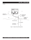
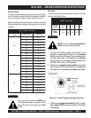
Connect the terminal of the ground wire between the
lock washer and the nut at the base of the generator
and tighten the nut fully. Connect the other end of the
ground wire to a
grounding rod
as shown in Figure 3.
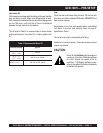
Circuit Breaker
To protect the generator from an overload,
a single-pole 40
amp circuit breaker is provided on the control box. Make
sure to switch this circuit breaker to the "OFF" position prior
to starting the engine.
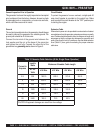
Extension Cable
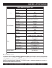
When electric power is to be provided to various tools or loads at
some distance from the generator, extension cords are normally
used. Cables should be sized to allow for distance in length and
amperage so that the voltage drop between the generator and
point of use (load) is held to a minimum. Use the cable selection
chart (Table 2 ) as a guide for selecting the proper extension
cable size.
GLW-180H — PRE-SETUP
)noitarepOesahPelgniS,zH06(noitceleSelbaCnoisnetxE.2elbaT
nitnerruC
serepmA
nIdaoL
sttaW
htgneLelbaCelbawollAmumixaM
021tA
stloV
eriW01#eriW21#eriW41#eriW61#
5.2003.tf0001.tf006.tf573.tf052
5006.tf005.tf003.tf002.tf521
5.7009.tf
053.tf002.tf521.tf001
010021.tf052.tf051.tf001
510081.tf051.tf001.tf56
020042.tf521.tf57.tf05
.egatlovwolmorftlusernaceg
amadtnempiuqE:NOITUAC


