


GLW-180H A.C. GENERATOR/WELDER — PARTS & OPERATION MANUAL — REV. #5 (03/14/05) — PAGE 19
GLW-180H — WELDER OPERATING INSTRUCTIONS
CAUTION:CAUTION:
CAUTION:CAUTION:
CAUTION:
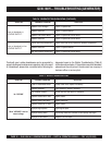
To prevent serious accidents, ALWAYS turn
off the generator/welder ( operation switch)
and set the main circuit breaker to the OFF
position.
NEVER
switch the
current range
selector
switch
during any welding operation.
CAUTION:CAUTION:
CAUTION:CAUTION:
CAUTION:
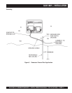
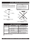
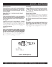
1. Connect the welding cables (electrodes) to the
generator's output terminals (Figure 4). For
minimum
welding current (min-130 amps), use an eyelet terminal
connector with a 5/64" to 1/8" diameter, for
maximum
welding current (110 - max amps), use an eyelet terminal
connector with a 3/32" to 5/32" diameter
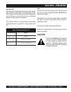
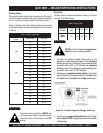
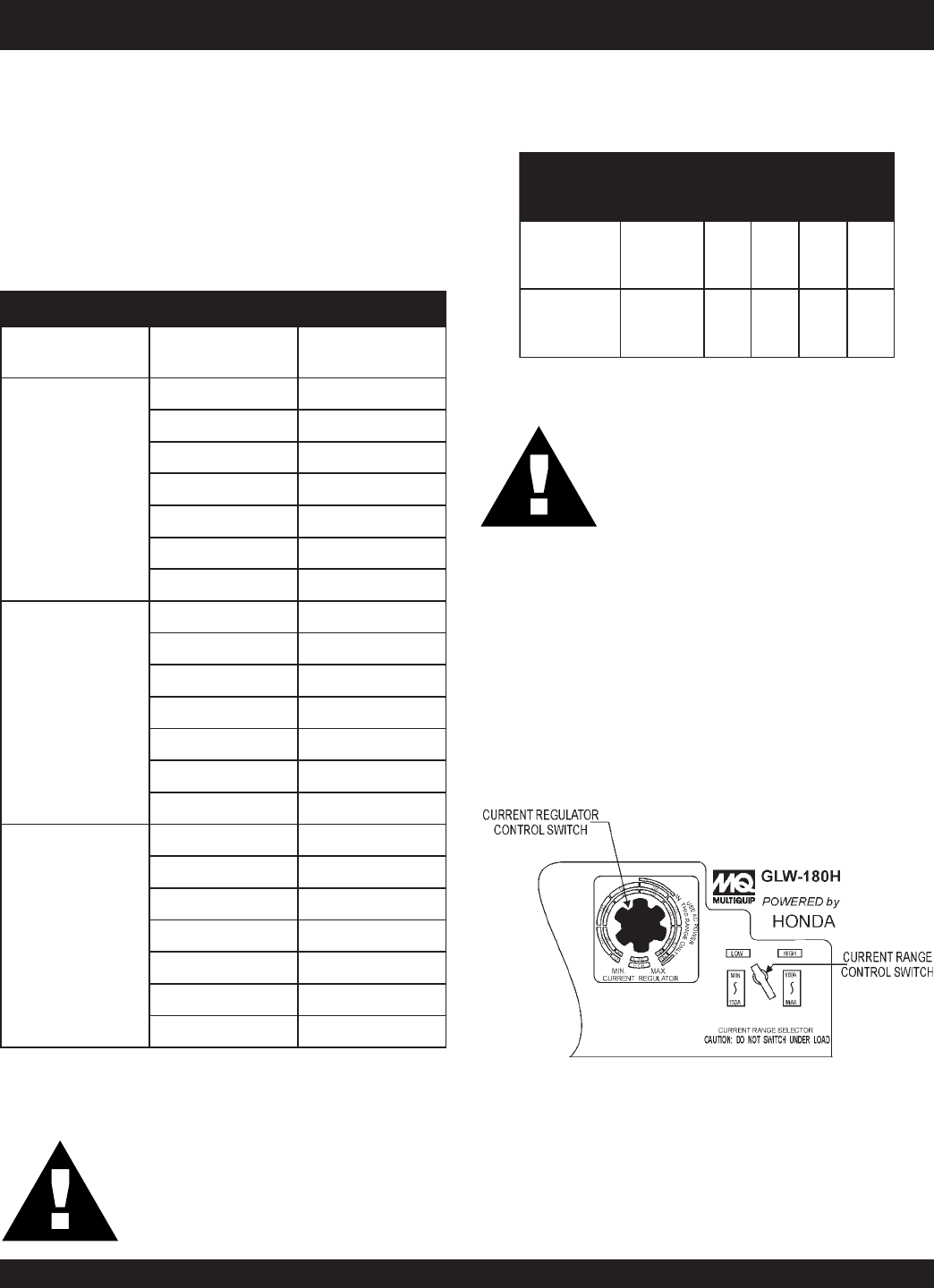
2. Set the current
regulator control switch
on the control
panel (Figure X) to the desired setting. The
inner
scale
is for
low
current, the
outer
scale is
high
current output.
Figure 6. Current Regulator/Range Switches
3. Set the current
range control switch
(Figure 7) to either
low
or
high
. DO NOT change the position of this switch
while welding.
Welding Cables
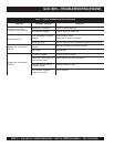
The required cable welding size is governed by this simple
rule: The longer the welding cable, or the greater the welding
current, the thicker (copper strands) the calbe must be.
Select a welding cable with adequate thickness according
to the cable length and welding amperage (current) as listed
in Table 5.
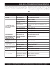
Duty Cycle
The duty cycle for the generator/welder is based on 10 minute
intervals. See Table 6 below.
seziSelbaCredleW.5elbaT
tuptuOredleW
tnerruC
htgneLelbaCeziSelbaC
001
053.oN
0013.oN
5213.oN
0513.oN
0023.oN
0523.oN
0033.oN
051
053.oN
0013.oN
5213.o
N
0513.oN
0022.oN
0521.oN
0031.oN
002
053.oN
0013.oN
5213.oN
0512.oN
0021.oN
0520/1.oN
0030/1.oN
elcyCytuD.6elbaT
gnidleW
tnerruC
ro011
sseL
521541061081
ytuD
%elcyC
00108060504