


PAGE 22 — HTXD6i/STXD6i TROWEL • SETUP, ADJUSTMENTS AND CALIBRATIONS — REV. #1 (01/24/14)
8. Retighten jam nut.
9. Return engine to idle.
10. Turn off machine and remove gauge.
11. Record Pressure on Machine Information and
Maintenance Log.
12. Re-enable cold start.
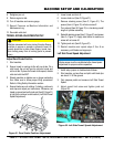
TROWEL SPEED ADJUSTMENT\SETUP
Adjust Zero Stroke Position
1. Start machine.
2. Ensure trowel is running at idle with no stroke. On a
cold trowel, the unit will go into cold start mode and
not be at idle. To place the trowel at idle speed, disable
cold start with the WST.
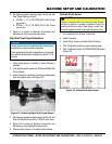
3. Elevate machine so blades are no longer contacting
floor. Make sure to follow proper lifting procedures.
Refer to Lifting Safety Information section.
4. Ensure blades are not rotating. If rotating, continue to
next step and adjust per instructions. Otherwise, set
trowel on ground and verify jamb nut (Item D, Figure 31)
is tight then continue to next section (Left Side Trowel
Speed Adjustment).
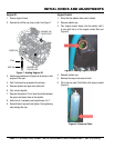
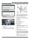
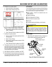
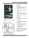
Figure 31. Zero Stroke Position Adjustment
CAUTION
Machine movement will occur during this step. Ensure
machine is secure or operator is present in seat. All
guards should be in place. Keep fingers, hands, hair,
and clothing away from all moving parts to prevent
injury.
E
D
C
A
B
MACHINE SETUP AND CALIBRATION
5. Lower trowel and shut off.
6. Loosen Jamb nut (Item D, Figure 31).
7. Remove retaining screw (Item C, Figure 31). The
spacer (Item A, Figure 31) will also come off.
8. Turn rod end (Item B, Figure 31) in, shortening overall
length of cylinder assembly.
9. Reinstall retaining screw (Item C, Figure 31) and spacer
(Item A, Figure 31). Apply blue loctite to make sure
screw will not come off.
10. Tighten jamb nut (Item D, Figure 31).
11. Restart machine and repeat steps 2 thru 8 as
necessary, until blades no longer spin.
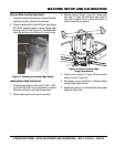
Left Side Trowel Speed Adjustment
1. Install setup jumper or disable stroke follower.
2. Start machine, on bare floor and pitch until blade tips
are about ½” off the ground.
3. Fully depress pedal and measure Left Side Trowel
Speed.
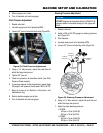
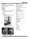
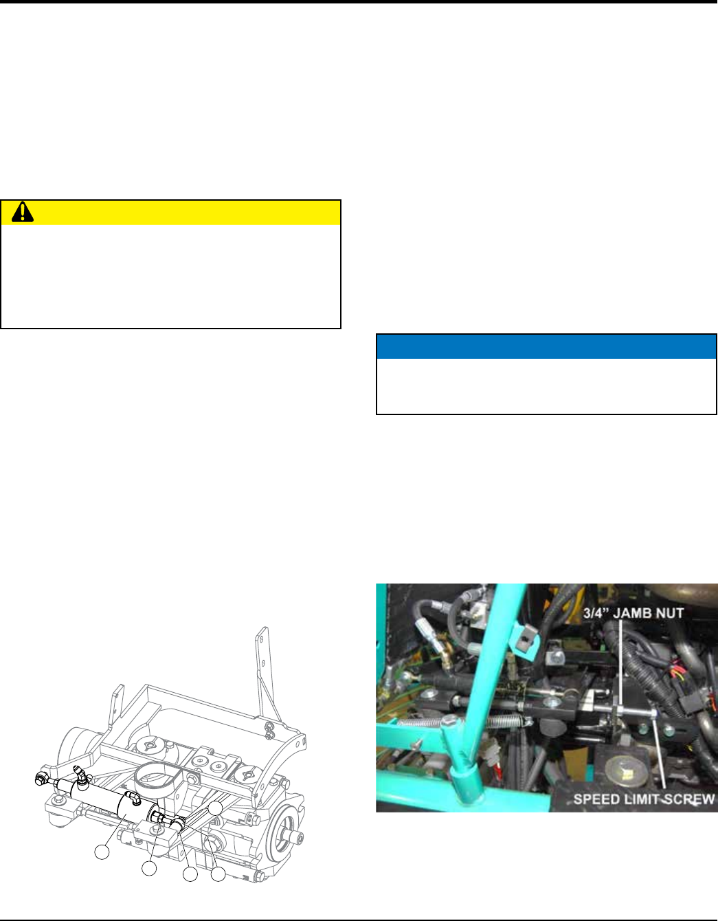
4. Adjust speed limit screw and tighten jamb nut
(Figure 32).
Figure 32. Left Side Trowel Speed Adjustment
NOTICE
Stroke sensor must be recalibrated after trowel speed
adjustment for proper machine operation.