


HTXD6i/STXD6i TROWEL • SETUP, ADJUSTMENTS AND CALIBRATIONS — REV. #1 (01/24/14) — PAGE 25
MACHINE SETUP AND CALIBRATION
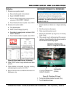
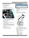
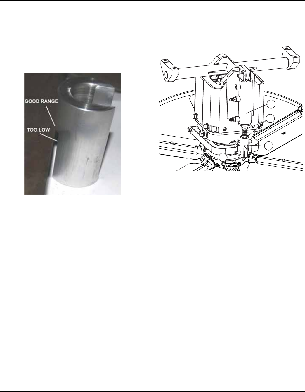
Measure Blade Leading Edge Height
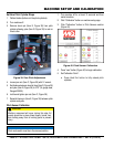
1. Fully pitch machine by pressing and holding Twin pitch
up button until pitch cylinders fully extended.
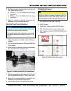
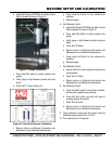
2. Choose a blade on both LH and RH Rotor. Using Gauge
P/N 32044, measure height of raised leading edge
ensuring it is 2.00” ±.060” (Figure 37). If the blade slides
under the first step but not the next, it is within limits.
Figure 37. Measuring Leading Edge Height
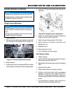
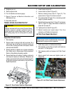
Leading Edge Height Adjustment
1. If leading edge height is within limits (2.000” ± .060”)
for left and right side, then no adjustment is needed.
Otherwise, proceed to next step for adjustment.
2. Flatten blades (bottom out the pitch cylinders).
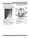
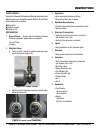
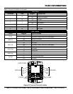
3. Remove clevis pin (Item E, Figure 38). Loosen jamb
nuts (Item C, Figure 38) and adjust clevis (Item D,
Figure 38) to cylinder (Item A, Figure 38) position, to
raise or lower pitch as required.
Figure 38. Blade Leading Edge
Height Adjustment
4. Tighten jamb nuts(Item C, Figure 38) and reinstall
clevis pin (Item E, Figure 38).
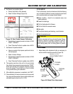
5. Re-measure as per instructions in “Measure Blade
Leading Edge Height” section.
6. Repeat steps 2 thru 5 until Left and Right leading edge
height are within limits.
A
E
D
C