


MQ SP-3035 CONCRETE SAW — OPERATION AND PARTS MANUAL — REV. #3 (09/29/06) — PAGE 60
MQ SP-3035 CONCRETE SAW
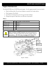
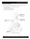
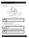
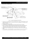
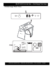
Positraction Adjustment
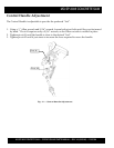
Fig. 47 — Positraction Adjustment Bolt Locations
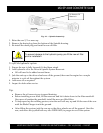
1. Lift Saw 4” to 6” and tilt forward to place spindle flanges on ground. When flanges are on the
ground, depress Raise Button to raise the rear of the saw to full height. Use suitable stands to
hold rear of saw up.
2. Disengage Positraction Lever fully.
3. Loosen Positraction clamping plate bolts enough to adjust Positraction assembly.
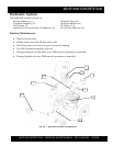
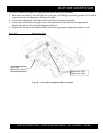
4. Insert 1/8” flat spacer between Positraction drive hub and rear wheel on both sides. Use a
finger-type clamp to compress the drive hub and the rear wheel, insert spacers between
contact points of wheel and hub. Tighten clamp until rear wheel compresses slightly.
5. Tighten Positraction clamping bolts to secure Positraction assembly. Remove clamps and
spacer.
6. Remove supports. Grasp the handlebars securely and depress the “Lower” button until the
rear of the saw has lowered sufficiently to safely lower the rear wheels to the ground.
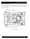
Clamp Plate Bolt
Clamp Position
(Inside Wheel Lip)
Clamp Plate Bolt
Clamp Position
(Inner Lip of Drive Hub)
Spacer Position