


www.norcold.com/cda
42
Refrigerator Service ManualN6XX/N8XX Models
Installation of Replacement Cooling Unit
N64XIM/N84XIM (ice maker)
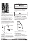
a. Remove the ice maker water line.
b. Disconnect the ice maker wire harness wires
(white and brown wires) from the water valve
solenoid.
c. Disconnect the ice maker wire harness ground
wire.
d. Move the wire harness out of the way.
e Remove the water valve.
N62XF/N82XF/N64XF/N84XF (fan models)
• Remove the fan, bracket, thermostat, and wiring
from the cooling unit.
1. Remove the drip cup retaining screw, then remove
the cup.
2. Remove the burner box cover retaining screw, then
remove the cover.
3. Disconnect the burner tube from the gas valve at the
gas valve.
4. Remove the burner retaining screw.
5. Remove the burner tube and burner from the burner
box.
6. Disconnect the gas valve wires from the power
board.
7. Remove the gas valve assembly (including bracket).
8. Loosen the spark/sense electrode assembly
retaining screw and remove the assembly from the
burner box.
10. Remove the rear mounting flange screws.
11. Pull the refrigerator from the enclosure.
12. Remove the burner box retaining screws, then
remove the burner box.
3-way refrigerators (AC/LP/DC)
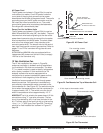
• Disconnect the DC heater wire leads from power
board terminals FLP/DC HEAT and DC_HT GND.
13. Disconnect the AC power cord from the power
board.
14. Remove the power board cover retaining screws,
then remove the cover.
15. Disconnect the AC heater wires from power board
terminals AC_HT -LO1 and AC_HT_HI.
3-way refrigerators (AC/LP/DC)
• Remove DC heater (3-way models only). Retain
the heater for reinstallation.
16. Remove the thermistor from the 10th fin.
17. Remove eight retaining screws along with washers
from the freezer plate.
15. Remove four retaining screws from the fin assembly.
16. Cut or remove the tape around the edge of the foam
plug.
17. Remove two absorber bracket retaining screws.
18. Separate the cooling unit from the refrigerator
cabinet. To separate:
a. Grab the cooling unit by the liquid heat exchanger.
b. Pull cooling unit upward at a slight angle to
unseat the foam plug.
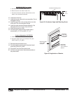
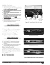
19. Remove the condenser retaining screw. See Figure
29, page 43.
20. Pull the cooling unit from the cabinet.
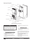
Removal of Cooling Unit
1. Clean the old sealant from the back of the
evaporator plate, fin assembly, cooling unit, and
the cabinet step.
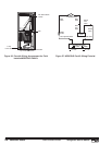
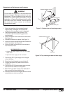
2. Apply a 1/2 inch bead of sealant to the cooling unit
low and the high temperature evaporators, and to
the foam plug step. See Figure 30.
3. Mate the cooling unit foam plug section with the
cabinet step opening. The foam plug must seat
evenly against the cabinet step.
4. Fasten the condenser section to the cabinet. Do
not overtighten the condenser retaining screw
Figure 29, page 43.
5. Fasten the freezer plate to the cooling unit (eight
screws with washers). Do not overtighten the
freezer plate screws.
6. Fasten the fin assembly to the cooling unit (four
screws). Do not overtighten fin screws.
7. Attach the thermistor to the 10
th
fin (counting from
right to left).
8. Fasten the absorber section of the cooling unit to
the cabinet (two screws). Do not overtighten
retaining screws.
9. Tape the edge of the foam plug to the cabinet . Use
HVAC metallic tape or heavy duty duct tape.
N62XF/N82XF/N64XF/N84XF (Fan models)
• Reinstall the fan bracket, fan, thermostat, and
wiring. See wiring diagram on the outer surface of
the fan bracket or refer to Figure 27, page 36.
The sealant must be applied correctly to prevent air
from being drawn into the cooling unit's high and low
evaporators.
NOTE