


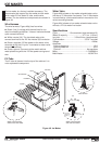

www.norcold.com/cda 69N6XX/N8XX ModelsRefrigerator Service Manual
D
O
N
O
T
R
O
T
A
T
E
M
A
N
U
A
L
L
Y
V
L
T
H
M
N
DISCONNECT POWER
TO REMOVE MODULE
U
R
185W-115V-60 HZ
IM # S 106 626649
11 MAY 00
WB1
Shut-Off Arm
(ON position)
MIN MAX RANGE HOLD
H
HzREL
mA
A
mV
V
V
OFF
!
!
A
COM
V
mA µA
1000V MAX
400mA MAX
FUSED
10A MAX
FUSED
PEAK MIN MAX
µA
CAT II
4 1/2 DIGITS
1 Seconds
87
TRUE RMS MULTIMETER
III
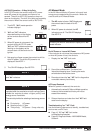
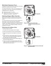
Water Fill Adjustment
The ice maker water fill adjustment is factory set.
Tampering with the water adjustment screw may cause
the water valve to close before the mold is filled to
normal level or exceed the mold water level. If the valve
closes before the mold is filled to capacity, the ice
cubes produced will be small and thin. If the water
valve remains open longer than 7.5 seconds, the water
level in the mold will be above the normal level. The
excess water above the normal level tends to form a
layer of ice that fuses all the ice cubes. The surface
tension created by the extra layer of ice prevents the
ejector from removing the ice cubes from the mold.
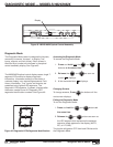
The water fill adjustment screw location is shown in
Figure 53, page 69. Turning the screw 1/4 turn in a
clockwise or counterclockwise direction varies the fill
by 0.34 fl. oz. (10 mL).
Turning the screw varies the location of the adjustable
internal copper contact. The small hole in the contact
should be in the center of the module housing hole
(alignment indicator). With the hole centered, the
water valve should remain open approximately 7.5
seconds.
Low Ice Yield
The thermostat initiates the cycle when the
temperature of the mold is approximately 14°F. For the
ice maker mold to reach 14°F, the freezer temperature
must be maintained at or below 0°F. In gas absorption
refrigerators low ice yield may be caused by poor
cooling unit ventilation, which will directly affects
freezer temperature.
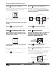
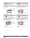
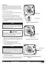
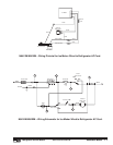
Water Valve Operation Test
Test water valve operation by shorting points V and L
using an insulated jumper wire. See Figure 54.
Shorting points V and L energizes the valve's solenoid.
When energized, the solenoid will make an audible
click and continuous buzzing sound until the jumper
wire is removed.
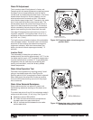
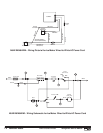
Water Valve Solenoid Resistance
Always disconnect the ice maker AC power cord
before taking resistance readings on the water valve
solenoid.
To contact test points V and N, the resistance meter's
probes must be at least 1/2 inch long. See Figure 55.
n Resistance values: 295 to 360 Ω.
n OL: check for loose wire harness connections at
the water valve or an open solenoid coil.
n 00.0 Ω: indicates a short between the ice maker
and the water valve.
Figure 54. Energizing water valve through test
points V and L.
Figure 55. Measuring water valve solenoid
resistance across points V and N.
295 to 360 ohms
D
O
N
O
T
R
O
T
A
T
E
M
A
N
U
A
L
L
Y
V
L
T
H
M
N
DISCONNECT POWER
TO REMOVE MODULE
U
R
185W-115V-60 HZ
IM # S 106 626649
11 MAY 00
WB1
Insulated jumper wire
(14 AWG with 1/2-stripped ends)