


page 16
Calibration Procedure
1. Requirements
The CDTX-90 Transmitter is factory calibrated using simulated input signals. System calibration will reduce errors caused by
sensor wire lengths longer than the standard 15 ft. length. Wire lengths of 100 feet are acceptable; cable shield must be
maintained through cable splice. Calibration may be done by known solution value (A), or by resistance simulation (B).
A) Calibration with NIST Traceable Solutions:
When using NIST traceable standards, ensure the sensor and test solution are at the solution temperature specified on the test
solution label. Prevent contamination of the calibration solution. Thoroughly rinse the sensor in a small amount of test solution
before placing in any test solution for calibration purposes.
B) Optional Verification with Precision Resistors:
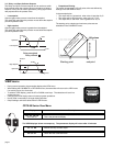
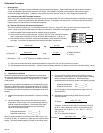
The use of precision resistors (±0.1%) connected to the rear "Temp In", "Signal IN", and "Iso Gnd" terminals in place of the
sensor, yields quick and accurate electronic instrument calibration. Calibration is completed as follows:
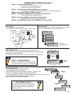
1) Select a standard cell constant based on desired range of operation.
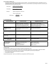
2) Place a 1096 Ω (25°C) resistor between "Temp IN" and "Iso. Gnd" terminals as shown.
Note: Temperature simulation errors can adversely effect calibration: 3.85 per °C.
3) Calculate the required simulation resistor that represents a value within the selected
cell range. The formula for determining the required simulation resistance is:
Resistance =
Sensor Cell
:
e.g.
0.1 Cell
= 5,000 Ω or 5 KΩ
Desired conductivity (Siemens*) 0.000020 (Siemens*)
Conductivity =
Sensor Cell
:
e.g.
0.1 Cell
=
0.000001 Siemens*
Simulation resistance (Ω) 100,000 (Ω)
or 1µS/cm
(*Conversion: 1 µS = 1 X 10
-6
Siemens or 0.000001 Siemens)
4) Place the calculated simulation resistance between the "Signal IN" and "Iso Gnd" terminals as shown.
5) Set temperature and set conductivity. (Optional: Reset to factory calibration by entering zero as the "Set Conductivity" value.)
Iso. Gnd
(BLACK)
Temp. IN
(WHITE)
Signal IN
(RED)
9
8
7
Simulation resistor
TC resistor
2. Temperature Coefficient
Conductivity measurement is highly dependent on temperature.
Temperature dependence is expressed as the relative change per
°C, commonly known as percent/°C change from 25°C, or slope
of the solution.
Slopes can very significantly depending on process solution type.
The factory default temperature compensation factor is 2.00%/°C.
Process solutions may require adjustment for maximum accuracy.
To determine the optimum temperature compensation factor for a
process:
1. Disable the temperature compensation % factor by entering
0.00.
2. Heat the sample solution close to the maximum process
temperature. Place sensor in the sample solution allowing
several minutes for stabilization. Access the VIEW menu
and record the displayed temperature and conductivity
values in the spaces provided:
Displayed temperature: T1 = _______ °C
Displayed conductivity: C1 = _______ °C
(Do not use this procedure for solutions from 0.055 µS to 0.1 µS
(10 MΩ to 18 MΩ). An internal pure water curve is used for these
ranges. The factory default setting of 2.00%/°C should be used.)
3. Cool the sample solution close to the minimum process
temperature. Place sensor in the sample solution allowing
several minutes for stabilization. Record displayed
temperature and conductivity values in the spaces provided:
Displayed temperature: T2 = _______ °C
Displayed conductivity: C2 = _______ °C
(A 10% change in conductivity between steps 2 and 3 is
recommended.)
4. Substitute recorded readings (steps 2 and 3) into the
following formula:
TC Slope =
100 x (C1 - C2)
(C2 x (T1 - 25)) - (C1 x (T2 - 25))
Example: A sample solution has a conductivity of 205 µS
@ 48°C. After cooling the solution, the conductivity was
measured at 150 µS @ 23 °C. (C1 = 205, T1 = 48, C2 =
150, T2 = 23)
The TC is calculated as follows:
TC Slope =
100 x (205 - 150)
=
5500
=
1.42%/°C
(150 x (48 - 25)) - (205 x (23 - 25)) 3860