


page 7
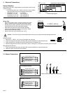
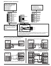
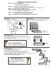
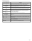
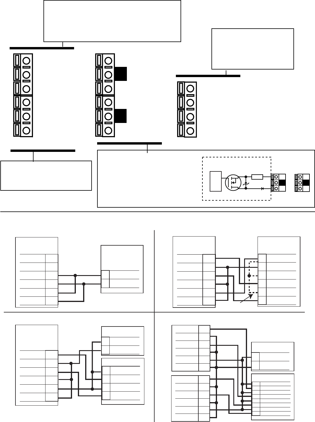
Stand-alone application, no current loop used
Transmitter
Terminals
6
5
4
3
2
1
Loop2-
Loop2+
Sys. Pwr.
Loop -
Sys. Pwr.
Loop +
AUX
Power -
AUX
Power +
Power Supply
DC 12 - 24 V
Power
Supply
Power
Supply
Connection to a PLC with built-in power supply
PLC
Terminals
Power Supply
Ground
Power
Supply
Channel 2
4-20 mA in
Channel 2
4-20 mA in
Channel 1
4-20 mA in
Channel 1
4-20 mA in
Internal PLC
Connection
NC
NC
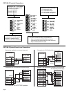
Connection to a PLC/Recorder, separate supply
PLC or Recorder
Channel 2
4-20 mA in
Channel 2
4-20 mA in
Channel 1
4-20 mA in
Channel 1
4-20 mA in
DC 12 - 24 V
Power
Supply
Power
Supply
PLC or Recorder
- Channel 4
+ Channel 4
- Channel 3
+ Channel 3
- Channel 2
+ Channel 2
- Channel 1
+ Channel 1
DC 12 - 24 V
Power
Supply
Power
Supply
Transmitter
Terminals
6
5
4
3
2
1
Loop2-
Loop2+
Sys. Pwr.
Loop -
Sys. Pwr.
Loop +
AUX
Power -
AUX
Power +
Transmitter
Terminals
6
5
4
3
2
1
Loop2-
Loop2+
Sys. Pwr.
Loop -
Sys. Pwr.
Loop +
AUX
Power -
AUX
Power +
6
5
4
3
2
1
Loop2-
Loop2+
Sys. Pwr.
Loop -
Sys. Pwr.
Loop +
AUX
Power -
AUX
Power +
6
5
4
3
2
1
Loop2-
Loop2+
Sys. Pwr.
Loop -
Sys. Pwr.
Loop +
AUX
Power -
AUX
Power +
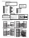
Transmitter 1 Transmitter 2
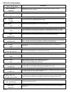
Example: Two transmitters connected to PLC/Recorder
with separate power supply
-
+
-
+
-
+
-
+
-
+
-
+
-
+
-
+
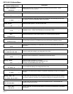
AUX power required for all CDTX-90 systems.
Sensr Gnd
(SHIELD)
Iso. Gnd
(BLACK)
Temp. IN
(WHITE)
Signal IN
(RED)
14
13
12
11
Output 2-
Output 2+
Output 1-
Output 1+
10
9
8
7
Loop 2-
Loop 2+
System Pwr
Loop -
System Pwr
Loop +
AUX
Power -
AUX
Power +
6
5
4
3
2
1
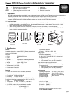
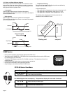
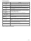
Terminals 7-10: Open-collector Outputs
•Two transistor outputs, programmable
as:
• High or Low setpoint with adjustable
hysteresis
• proportional pulse (to 400 pulses per
minute maximum)
• May be disabled (Off) if not used
Terminals 3-6: Loop Power
12-24 VDC ±10% system power and current loop output.
Max. loop impedance:
50 Ω max. @ 12 V
325 Ω max. @ 18 V
600 Ω max. @ 24 V
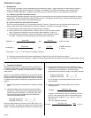
1
Internal open-collector
output circuit
Outputs
Isolation
15Ω
S
D
2
_
+
Terminals 1-2: Auxiliary power
Provides DC power to measurement
circuit. Required for all CDTX-90
systems.
CDTX-90-3 System Power/Loop Connections
CDTX-90-3 Terminal Connections
Terminals 11-14: Sensor input
11 is conductivity input
12 is temperature input
13 is the isolated signal ground
14 is the sensor earth ground