


page 3
CAUTION!
• Remove power to unit before wiring
input and output connections.
• Follow instructions carefully to avoid
personal injury.
Omega CDTX-90 Series Conductivity/Resistivity Transmitter
Contents
1. Installation
2. Specifications
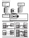
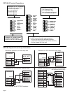
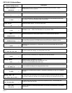
3. Electrical Connections
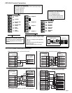
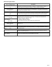
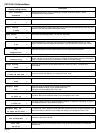
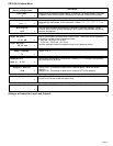
4. Menu Functions
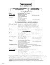
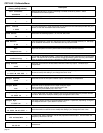
2. Specifications
General
Compatible electrodes: Omega CDCE-90 Series Standard and
Certified Series Conductivity/Resistivity Electrodes
Accuracy: ±2% of reading
Enclosure:
• Rating: NEMA 4X/IP65 front
• Case: PBT
• Panel case gasket: Neoprene
• Window: Polyurethane coated polycarbonate
• Keypad: Sealed 4-key silicone rubber
• Weight: Approx. 325g (12 oz.)
Display:
• Alphanumeric 2 x 16 LCD
• Contrast: User selected, 5 levels
• Update rate: 1.8 seconds
Electrical
• Power: 12 to 24 VDC ±10%, regulated, 80 mA max.
Sensor input range:
• Conductivity: 0.055 to 400,000 µS
• Resistivity: 10 KΩ to 18.2 MΩ
( Measurements from 10 MΩ to 18 MΩ (0.055 µS to 0.1 µS) must
be performed in solution temperatures from 20 °C to 100 °C. )
• TDS: 0.023 to 200,000 ppm
• Temperature: PT 1000, -25 to 120°C (-13 to 248°F)
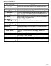
Current output:
•4 to 20 mA, isolated, fully adjustable and reversible
• Max loop impedance: 50 Ω max. @ 12 V
325 Ω max. @ 18 V
600 Ω max. @ 24 V
• Update rate: 200 mS
• Accuracy: ±0.03 mA @ 25°C, 24 V
Relay outputs
(CDTX-90-2 includes 2 mechanical SPDT contacts):
• Maximum voltage rating:
5 A @ 30 VDC, or 5 A @ 250 VAC, resistive load
• Programmable for:
• High or Low setpoint with adjustable hysteresis
• Pulse operation (max. rate 400 pulses/min)
Open-collector output, optically isolated:
• 50 mA max. sink, 30 VDC maximum pull-up voltage.
• Programmable for:
• High or Low setpoint with adjustable hysteresis
• Pulse operation (max. rate 400 pulses/min)
Environmental
• Operating temperature: -10 to 70°C (14 to 158°F)
• Storage temperature: -15 to 80°C (5 to 176°F)
• Relative humidity: 0 to 95%, non-condensing
• Maximum altitude: 2000 m (6562 ft)
• Insulation category: II
• Pollution degree: 2
Standards and Approvals
• CSA, CE, UL listed
• Immunity: EN50082-2
• Emissions: EN55011
• Safety: EN61010
• Manufactured under ISO 9001 and ISO 14001
• U.S.A. Patent # 5,708,363
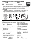
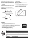
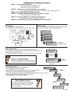
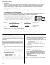
1. Installation
CDTX-90 Series transmitters are available in two styles: panel mount and field mount. The panel mount is supplied with the
necessary hardware to install the transmitter. This manual includes complete panel mounting instructions.
Field mounting requires a separate mounting kit. The FP90UM Universal kit enables the transmitter to be installed virtually
anywhere. Detailed instructions for field installation options are included with the FP90UM Universal kit.
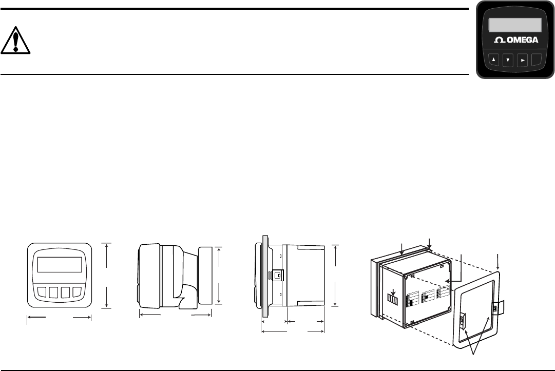
1.1 Panel Installation
1. The panel mount transmitter is designed for installation using a 1/4 DIN Punch. For manual panel cutout, an adhesive
template is provided as an installation guide. Recommended clearance on all sides between instruments is 1 inch.
2. Place gasket on instrument, and install in panel.
3. Slide mounting bracket over back of instrument until quick-clips snap into latches on side of instrument.
4. To remove, secure instrument temporarily with tape from front or grip from rear of instrument. DO NOT RELEASE.
Press quick-clips outward and remove.
SIDE VIEW
92 mm
(3.6 in.)
97 mm
(3.8 in.)
56 mm
(2.2 in.)
41 mm
(1.6 in.
)
Optional
Rear
Cover
Field Mount
Panel Mount
FRONT VIEW
96 mm
(3.8 in.)
96 mm
(3.8 in.)
quick-clips
gasket
panel
terminals
mounting
bracket
latch
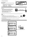
O
u
t
p
u
t
-
O
u
t
p
u
t
+
S
y
s
t
e
m
P
w
r
L
o
o
p
-
S
y
s
t
e
m
P
w
r
L
o
o
p
+
2
1
4
3
S
e
n
s
r
G
n
d
(
S
H
I
E
L
D
)
S
e
n
s
r
I
N
(
R
E
D
)
S
e
n
s
r
V
+
(
B
L
A
C
K
)
7
6
5
SIDE VIEW
Field Mount &
Panel Mount
Panel Mount
Installation Detail
106 mm
(4.18 in.)
82 mm
(3.23 in.)
Conductivity/Resistivity
62.50 uS/cm
25.0°C
ENTER