


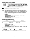
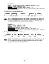

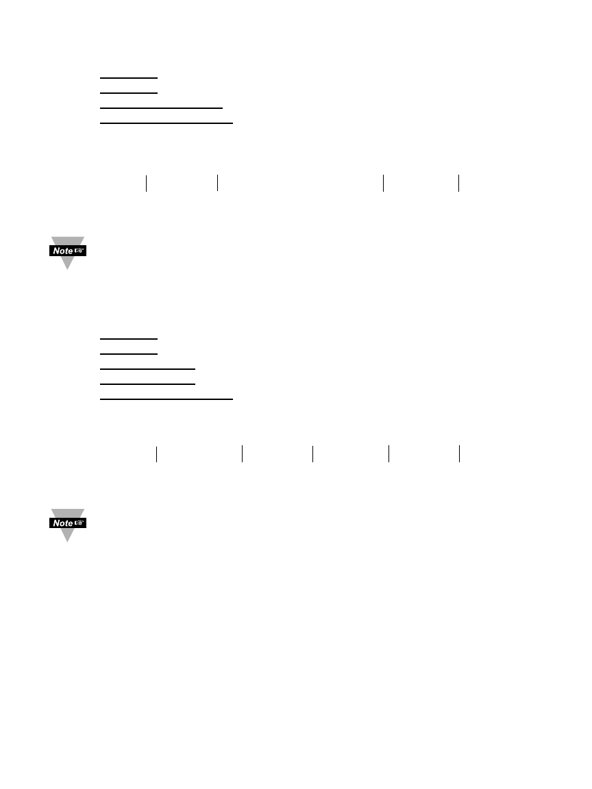
Example 3:
Output 1 = Analog Output (Alarm 1 disabled), Setpoint 1 = 300,
Output 2 = Relay, Setpoint 2 = 200
Alarm 1 & 2 Setup: Deviation, Band, “ALR.H” = 10
Color Display Setup: “N.CLR” = Green, “1.CLR” = Amber, “2.CLR” = Red
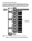
Display Colors change sequences:
AMBER AMBER AMBER GREEN AMBER
•➤
---------------
•
------
•
------
•
--------------------------------
•
------
•
-------
•
----------------
➤
0 190 200 210 290 300 310
Alarm 1 is designed to monitor the Process Value around the Setpoint 1.
Alarm 2 is designed to monitor the Process Value around the Setpoint 2.
If Analog Output Option board is installed (Alarm 1 is disabled), only
Alarm 2 is active and only two colors are available.
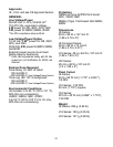
Example 4:
Output 1
= Relay, Setpoint 1 = 200
Output 2
= Relay, Setpoint 2 = 200
Alarm 1 Setup
: Deviation, Band, “ALR.H” = 20
Alarm 2 Setup: Deviation, Hi/Low, “ALR.H” = 10, “ALR.L” = 5
Color Display Setup
: “N.CLR” = Green, “1.CLR” = Amber, “2.CLR” = Red
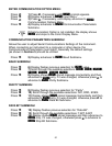
Display colors change sequences:
AMBER RED GREEN GREEN RED AMBER
•
--
➤
---------------
•
----------------
•
-------------
•
--------------
•
-------------
•
---------------------
➤
0 180 195 200 210 220
Reset: The instrument automatically resets after the last menu of
the Configuration Mode has been entered. After the instrument
resets, it advances to the Run Mode.
58